10 questions — reveal the final answers. Full worked solutions: the book.
2007 Q22007Waves and Optics · Two-dish radio interferometer observing the Sun
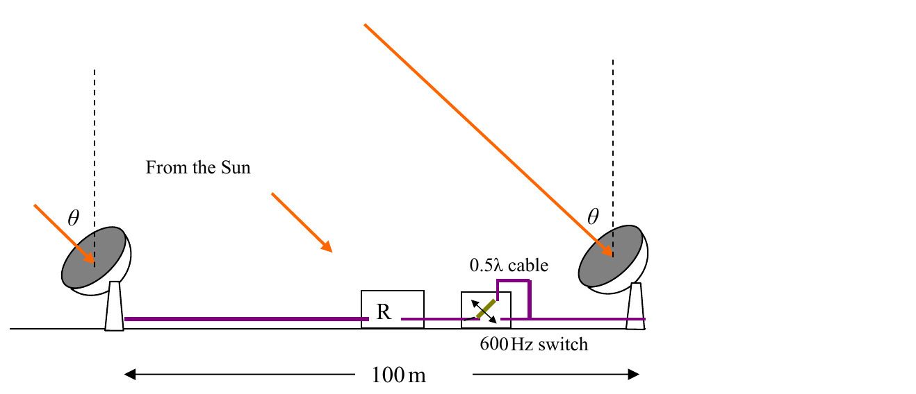
Figure 2.1
Figure 2.1 illustrates two radio telescope aerials on whose dishes fall part of a radio beam from the quiet Sun. The signals from the dishes are added together in the receiver. The beam makes an angle of $\theta$ degrees with the local vertical. The line joining the telescopes is on an E--W line on the equator. The receiver, R, accepts waves of a frequency of $150\ \mathrm{MHz}\pm1.00\ \mathrm{MHz}$. Consider the date to be March 22nd.
(i) Normal broadcast receivers have a bandwidth of $\pm 25$ kHz. Why has the radio telescope receiver a much wider bandwidth?
(ii) Initially the dishes are simply connected to the receiver by equal length cables and the receiver sums the two signals. Show that the signal amplitude has a very slow component that varies given by,
$$I=I_{0}\cos\omega t ,$$
at time $t$, around midday. Find the value of $\omega$.
(iii) Sketch a graph showing how the maximum intensity of the signal varies with time between 1000 hrs and 1400 hrs on the 21st of September.
(iv) Sketch on the same graph how the maximum intensity of the signal varies with time between 1000 hrs and 1400 hrs on the 21st of June.
(v) In a modified arrangement a length of cable equivalent to half a wavelength is inserted and removed at a frequency of 600 Hz. After the receiver there is a further amplifier that is so tuned that it amplifies the 600 Hz signal. How will the amplitude of the 600 Hz signal vary with $\theta$?
(vi) Why is the modified scheme better?
Note. Bandwidth is loosely defined as the difference between the highest frequency received by a receiver and the lowest frequency received when it is set to receive a certain frequency $f_{0}$. If $2\Delta f$ is the bandwidth then the highest frequency received is $f_{0}+\Delta f$.
(iii)The sketch is symmetric about midday, has a central maximum, and consists of fringes whose spacing is about $275\ \mathrm{s}$ near midday and becomes slightly wider towards 1000 and 1400.
(iv)This curve has the same central maximum and the same peak intensity, but its fringes are wider by the factor $1/\cos23.5^\circ\simeq1.09$.
2008 Q22008Waves and Optics · Acoustic echoes in a domed mosque
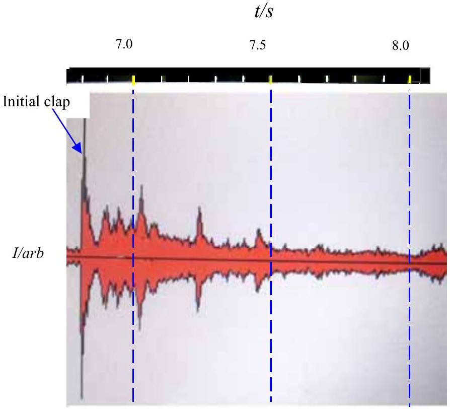
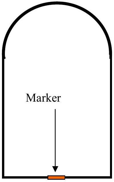
a) Figure 2.1b shows a simplified cross section of the Jamie mosque in Isfahan in Iran (venue of the International Olympiad in 2007). On the floor of the mosque there is a metal marker. If one claps one's hands near the marker it is suggested that multiple echoes should be heard. A digital camera was placed on the marker. Hands were clapped and the sounds recorded by a digital camera in "movie mode". Figure 2.1a shows a recording of the intensity of the sound. A time scale is shown in Figure 2.1a. There was a discussion amongst the physics leaders as to whether the marker is at the centre of the circular dome (if it is circular in cross section) or at the focus of the dome. N.B the sketch in Figure 2.1b is not to scale or correct proportion.
(i) Is the marker at the focus or the centre of curvature of the dome you can assume is spherical? How is it possible to decide this from the given data?
\{ii) Use the information given to determine the height of the centre of the interior of the dome. Carefully estimate the errors.
(iii) The intensity of sound, $I$, is given by
$$I=I_{o} \operatorname{Sin}(\omega t),$$
$\omega$ is the angular frequency, $I_{o}$ is the max intensity, a constant, and $t$ is the time.
It is suggested that the max intensity of the sound at the first reflection ( $I_{1}$ ) is related to that of the second reflection ( $I_{2}$ ) by an equation mathematically similar to that of radioactive decay measured at equal time intervals i.e.
$$\frac{I_{o}}{I_{1}}=\frac{I_{1}}{I_{2}} .$$
By analysing the diagram Figure 2.1a find evidence to support, or reject, this assertion. Explain why your conclusion should be expected on theoretical grounds.
2011 Q32011Waves and Optics · Bow waves and Cherenkov radiation
(a) An electron is accelerated in an evacuated chamber. Sketch lines that illustrate how the magnetic field produced by the electron will vary with time.
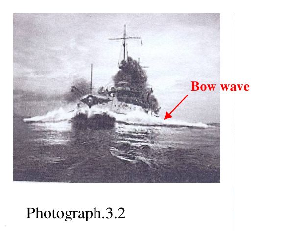
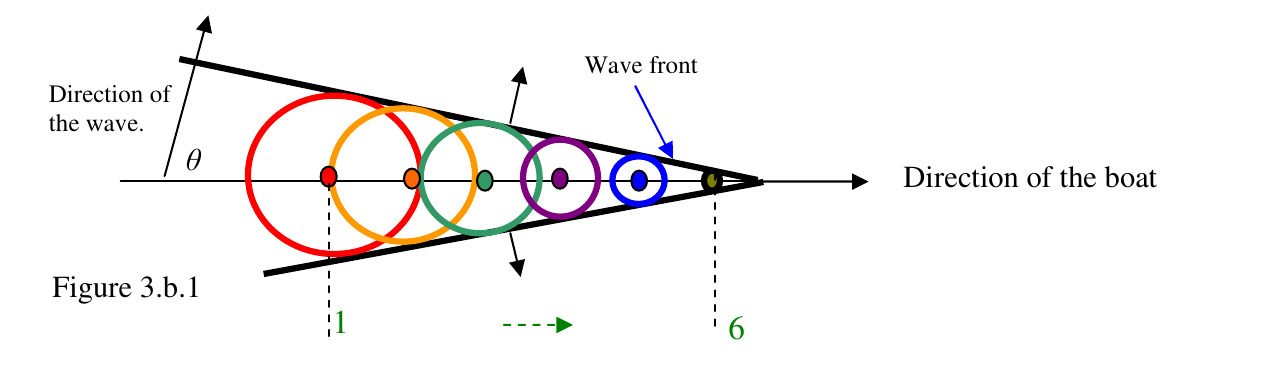
(b) It is possible that charged particles can go through a medium such as water or glass faster than the speed of light in that medium. Consider a boat travelling along on the surface of the water; the disturbance (the bow wave, Photograph 3.2) will spread in a way similar to the wave produced by a series of circles caused by small stones dropped in the water in succession, 1 to 6, equally spaced in time and distance. This is shown in Figure 3.b.1.
Find the value of the angle, $\theta$, that the bow waves make with the direction of the boat given that the speed of the boat is $5\ \mathrm{m\,s^{-1}}$ and the speed of the waves is $2\ \mathrm{m\,s^{-1}}$. The bow wave is illustrated in Photograph 3.2.
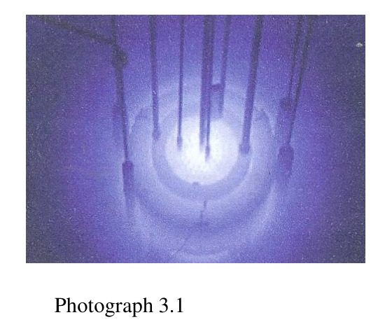
(c) Photograph 3.1 shows Cherenkov radiation, in the form of blue light, being produced by radioactive particles moving through water faster than the speed of light through water. Find a formula that relates the speed of the particles, $v_{p}$, to the refractive index of water, $\beta$ $\left(\beta=\dfrac{v_{p}}{c}\right)$ and $\theta$. Theta ($\theta$) is the angle that the emerging light makes with the incoming particle. Why is blue light observed?
(d) Use a very simple model to find how the Earth's temperature should vary with latitude. Comment how your model compares with what is observed.
Show answer · 显示答案
Final answers · 最终答案
(a)$B_{\mathrm{radiation}} =\frac{\mu_0 e a(t_{\mathrm{r}})\sin\alpha}{4\pi c r}$
2015 Q32015Waves and Optics · Road mirages: refraction in a temperature gradient
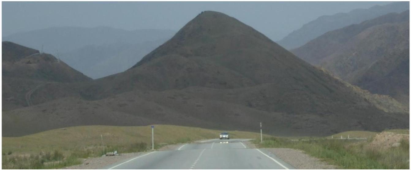
Whilst travelling in the one of the Stans after the end of the 2014 Physics Olympiad in Kazakhstan, the author noticed what appeared to be pools of water on the road and that the headlamps of the approaching vehicle seemed to be reflected in the road. However, this was surprising since the air temperature was about $36^{\circ} \mathrm{C}$ and it had not rained for some time. The refractive index of air at this temperature is about 1.0003 .
Briefly account for this phenomenon by means of a description and a diagram. Then consider numerical values to explain the magnitude of the effect.
Marks will be given for the derivation of a formula that gives the geometric path of the light.
The refractive index of the air, $n(z)$, is linearly related to the absolute temperature of the air, which varies linearly with height, $z$. You may assume that the refractive index has the form
$$n(z)=n(0)+\alpha z$$
$$\text { with, } \alpha z \ll 1$$
( $z$ is not measured from the road level)
Show answer · 显示答案
Final answers · 最终答案
Final resultThus an index variation of only about $10^{-5}$ across the hot surface layer is sufficient to produce the observed effect over the several-hundred-metre distances in the photograph.
(a) Large area optical reflecting telescope mirrors are needed if we are to see further into the universe. Greater light gathering capacity and increased resolving power do, however, mean that the mirror supporting structure must be increasingly expensive. One way to overcome this is to rotate a circular tank of clean liquid mercury at a constant rate to create the correct shape of mirror. Obtain an expression relating the angular frequency of rotation, $\omega$, and the $x-y$ coordinates of the mercury surface.
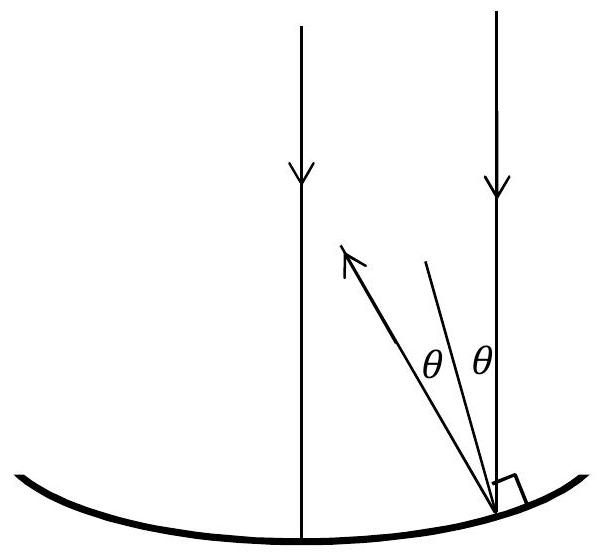
(b) A telescope mirror in the shape of a parabola can be specified by the equation $y=a x^{2}$. A ray parallel to the axis of the mirror is shown in Figure 3.1 below, with the normal and the reflected ray. Obtain an expression for $\tan 2 \theta$ in terms of $a$ and $x$.
You may find useful: $\cos 2 \theta=\cos ^{2} \theta-\sin ^{2} \theta$ and $\sin 2 \theta=2 \sin \theta \cos \theta$
(c) Show that the parabolic mirror will reflect all paraxial rays through a single focus, and determine the focal length of the mirror, $f$, in terms of $a$.
(d) The telescope is required to have a minimum resolution of (i.e. no worse than) 40 milliarcseconds in visible light. To avoid vibrations, the rate of rotation of the mercury mirror is a slow 8.5 revolutions per minute. If the mercury was rotated in a flat bottomed circular container with the same diameter as the mirror, estimate the minimum volume of mercury used to form the mirror.
(e) Mercury evaporates from the surface, as the molecules free themselves from the bulk of the liquid. The rate at which this happens is temperature dependent, but it is about $30 \mu \mathrm{~g}$ hour ${ }^{-1} \mathrm{~cm}^{-2}$. What fraction of the mercury mirror evaporates away in a week?
(f) The telescope mirror will focus light, but even for the ideal mirror shape, the light cannot be focused to a point. Explain why. If the intensity of light reaching the telescope from a distant source is $8.0 \times 10^{-14} \mathrm{~W} \mathrm{~m}^{-2}$ (a rather faint telescopic 13.7 magnitude star), what is an estimate of the maximum intensity of light which is obtained at the image position?
Show answer · 显示答案
Final answers · 最终答案
(a)$y=\frac{\omega^2}{2g}x^2$
(b)$\tan2\theta = \frac{4ax}{1-4a^2x^2}$
(c)$f=\frac{1}{4a}$
(d)Thus about $1.5\mathrm{\ m^3}$, or $1.5\times10^3$ litres, of mercury is required in this minimum-depth model.
2016 Q52016Waves and Optics · Diffraction by a helical spring (Photo 51)
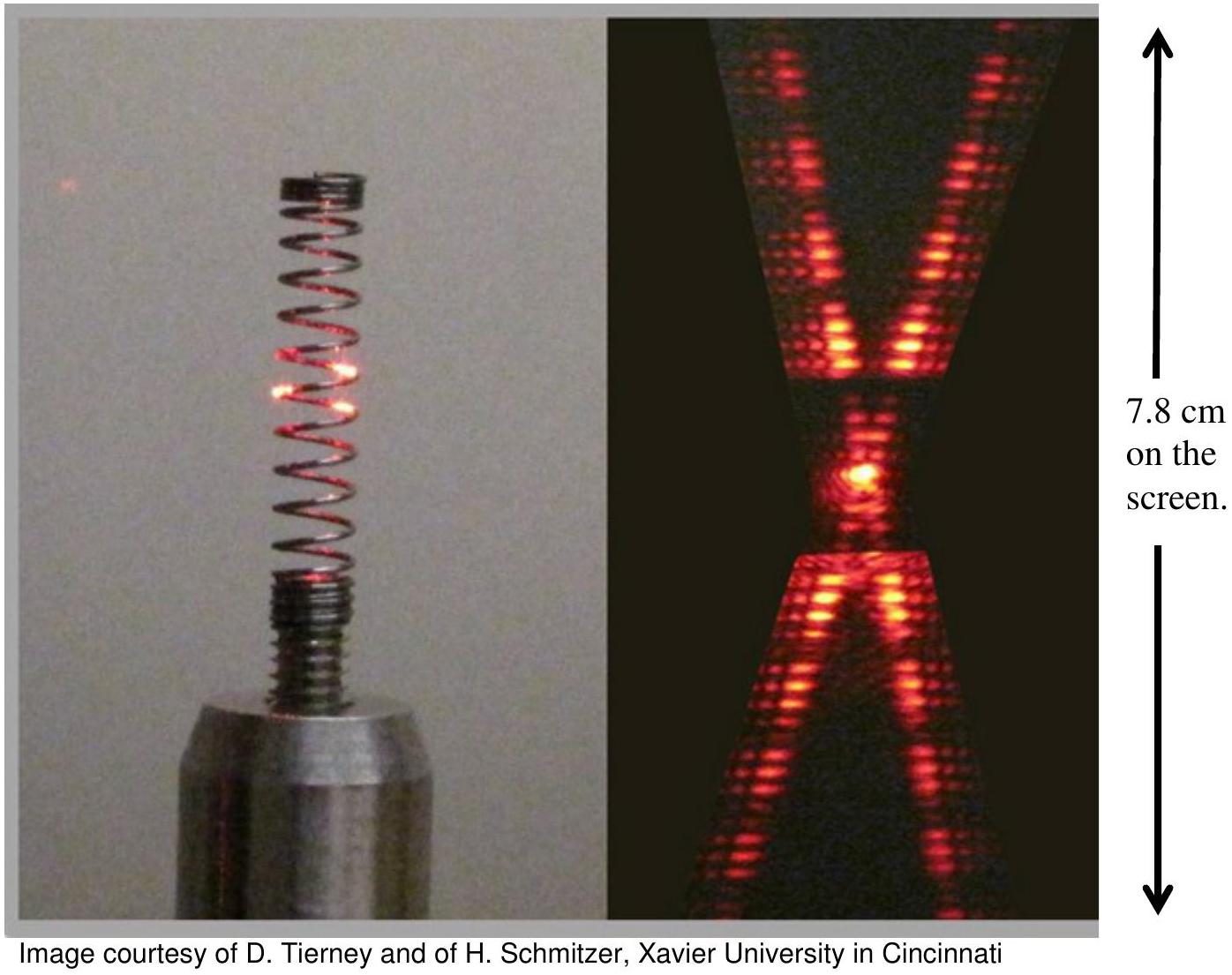
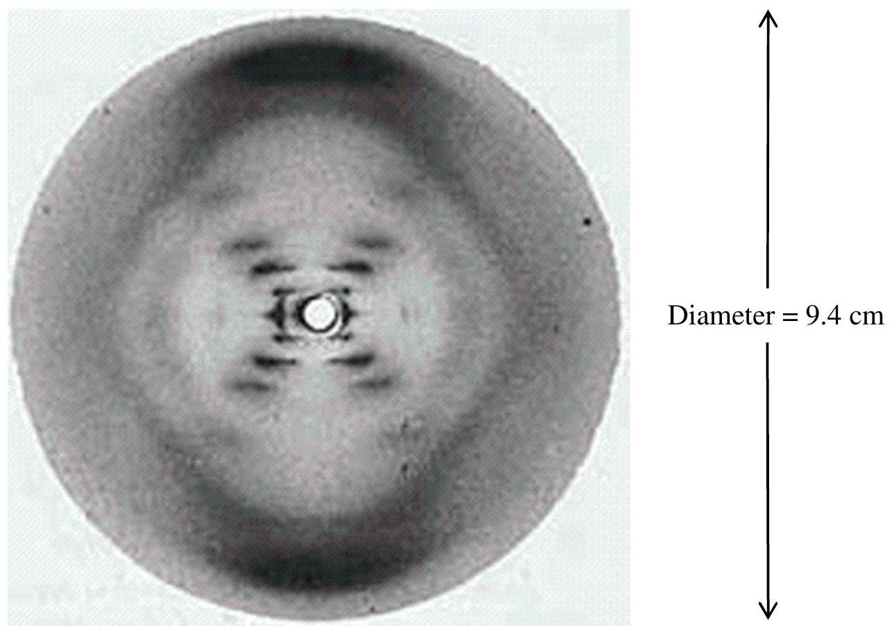
When illuminated with a laser pointer, the spring of a ballpoint pen produces a diffraction pattern which is similar to the famous Photo 51, the X ray diffraction image of DNA taken in May 1952 at King's College London.
The diffraction pattern of the spring (Figure 5.1) from a ball point pen is shown in Figure 5.2. It is illuminated using a red laser of wavelength of 633 nm . The scale of the diffraction pattern as it appears on the screen is given, but the size of the spring is unknown. The image is a height of 7.8 cm on a screen, which is at a distance of 4.2 m from the spring.
In diffraction, Babinet's principle states that the diffraction pattern of an obstacle is the same as the diffraction pattern of an aperture of the same shape. According to this principle, the diffraction pattern formed by the two straight sections of wire at an angle to each other is equivalent to the diffraction pattern of two single slits oriented at the same angle with respect to each other. The calculations of the angular positions of the maxima and minima will be exactly the same.
Figure 5.2 Diffraction pattern of the spring. The scale of the diffraction pattern is given.
The scale of the image is shown at the side, but this is not the same scale for the spring.
(a) Using the information given about the scale of the diffraction image, estimate the pitch of the spring, the thickness of the wire of the spring, and the radius of the spring.
(b) If Photo 51 was taken with the $\mathrm{K}_{\alpha}$ line of copper, which has a wavelength of 0.15 nm , and the distance between the sample and the film was 9.0 cm , estimate the angle, pitch and radius of the DNA molecule. In the image, the zeroth order is not visible in the centre. The first order maximum can just be seen, but the $2^{\text {nd }}, 3^{\text {rd }}$ and $5^{\text {th }}$ orders are clear. (The $4^{\text {th }}$ order is missing, an effect of the double helix structure, which you can ignore).
Show answer · 显示答案
Final answers · 最终答案
(a)The estimates for the spring are therefore pitch $1.7\mathrm{\ mm}$, wire thickness $0.33\mathrm{\ mm}$ and radius $0.90\mathrm{\ mm}$.
(b)Thus the estimates are angle $84^\circ$, pitch $3.9\mathrm{\ nm}$ and radius $0.69\mathrm{\ nm}$.
2018 Q42018Waves and Optics · Laser-driven light-sail probes: radiation pressure and focusing
It has been proposed that tiny probes could be sent to other stars by accelerating them away from Earth using a powerful laser.
(a). To push the probe hard enough for it to reach other solar systems will require a large laser focused on the sail of a small probe. One way of focusing the laser is to make use of existing optics by using a telescope in reverse. Given a telescope of diameter $D$ emitting a laser beam of wavelength $\lambda$, and a probe sail of diameter $d$, what is the distance $R$ the probe can get before less than $90 \%$ of the light hits the sail? How far is this for a sail of size 1 m , a telescope diameter of 10 m and a laser wavelength of 600 nm .
(b). Assume that when the monochromatic laser light hits the sail of the probe at right angles it has power $W$. What is the force $F$ exerted on a black (perfectly absorbing) sail and a silvered (perfectly reflective) sail? What is another major change in using a reflective sail?
(c). Using your previous expression, find the time it would take a probe of mass $m$ to travel a distance $L$. For simplification, you may assume that that the probe feels the full force of the laser beam up to distance $R$, and nothing after that, and that it has a perfectly reflective sail. The proposal calls for the probe to have mass of $10^{-3} \mathrm{~kg}$, the laser power to be 100 GW and for the probe to go to Alpha Proxima which is 4.2 light years away. Using the optics described in the first part, how long will this take?
(d). One way of reducing this time considerably is to increase $R$ by using a different optical set up. Rather than using one telescope, several telescopes could be used together in order to create an interference pattern. What is the maximum possible effective diameter of such a setup? What would be the travel time to Alpha Centauri under this setup? Comment on the validity of any extra approximations you had to make in this case.
Show answer · 显示答案
Final answers · 最终答案
(a)$R \approx 2\times10^7\,\mathrm{m}$
(b)$F_{\rm reflective}=\frac{2W}{c}$
(c)$T \approx 300\,\mathrm{years}$
(d)This extrapolation predicts a speed of order $10c$, so it is not physically valid.
2020 Q32020Waves and Optics · Huygens' principle and single-slit diffraction
Write you answer starting on a new page for this question.
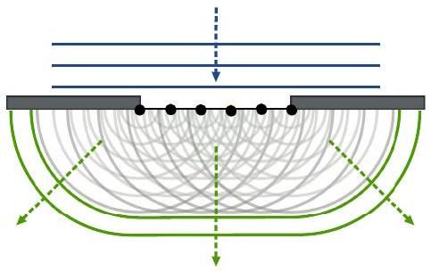
Huygens's wave theory states that each point on a wavefront can be treated as a secondary point source. A wavelet (a circular ripple) spreads out from each point and the new wavefront is formed by drawing a smooth line through all the fronts of these wavelets (an envelope enclosing all the wavelets). i.e. the superposition of all the smaller diverging wavelets emitted by the oscillating particles will form a new wavefront. This is illustrated in Fig. 5 below.
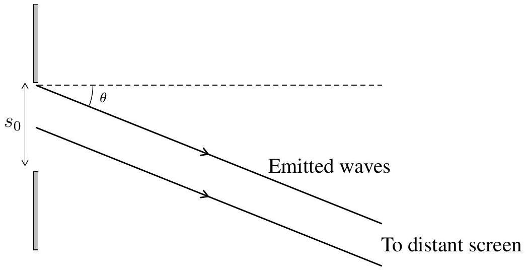
(a) Consider light diffracting through a single slit of width $s_{0}$ which is illuminated by a plane wavefront of uniform intensity and at normal incidence. We can determine the positions of the minima in a single slit pattern incident on a distant screen by considering the plane wavefront entering the slit to be constructed of a very large number of secondary points sources, each emitting circular wavelets (of light). In Fig 6 are shown two "emitted waves".
(i) Comment on the relation between these two rays and the secondary sources in the slit emitting wavelets.
(ii) At a certain angle, the path difference between rays emitted from the centre of the slit and the edge of the slit is $\lambda / 2$. Explain why the intensity of light falling on the screen in this direction is zero.
(iii) By splitting the slit into $1,2,3, \ldots$ parts and pairing up the rays, deduce all angles, $\theta$, for which the intensity of light falling on the screen is zero.
(iv) For a screen a distance $D$ away, where $D \gg s_{0} \gg \lambda$, deduce the fringe spacing of the diffraction pattern and the width of the central maximum.
(b) Finding the intensity of light on the screen as a function of angle $\theta$.
(i) Explain why the total (superposed) wave emitted by the slit at any angle will oscillate in phase with the wave travelling from the point at the very centre of the slit.
You might consider the secondary sources in the slit emitting waves which have the form of $A \cos (\omega t+\phi(\delta s))$ where $\phi(\delta s)$ represents the phase of a wave emitted from a point a distance $\delta s$ from the centre of the slit and in the plane of the slit.
(ii) Consider a wave incident on the slit with an amplitude dependent upon $\delta s$, taking the form $A(\delta s)=\frac{A_{0}}{s_{0}} \delta s$, where $A_{0}$ is the amplitude at the centre.
i. Sketch a graph of the amplitude of the wavefront from one side of the slit to the other.
ii. Sketch a graph of the intensity of the wavefront from one side of the slit to the other.
iii. Now taking a fixed amplitude $A_{0}$ across the slit, independent of $\delta s$, Show that the intensity of radiation as a function of $\theta$, where $\theta$ is the angle measured from the centre line normal to the slit, is given by
Hint: Choose a point in time when the 'height' of the wave emitted from the centre of the slit is maximised.
The limit of $\frac{\sin ^{2} x}{x^{2}}$ for $x=0$ is 1 .
(c) Numerical results for $I(\theta)$.
(i) Light from a red laser of wavelength 628 nm is normally incident on a single slit of width $20 \mu \mathrm{~m}$ after which the light strikes a screen 1.00 m away. Find the distance, on the screen, from the centre of the diffraction pattern to the brightest point of the first order maximum.
Hint: The brightest spots are not directly in the middle of the two adjacent minima. You may assume that the first non-zero positive solution to the equation $x=\tan x$ is, to four significant figures: $x=4.4934$
(ii) Find the ratio between the zeroth and first order maxima. At which order maximum does this ratio fall below $1 \%$ ?
Hint: Assume that for $n \geq 2$ the brightest point of a maxima falls roughly in the middle of the adjacent minima.
2021 Q42021Waves and Optics · Electromagnetic waves: travelling and standing waves
A travelling electromagnetic wave consists of oscillating electric and magnetic field components at right angles to each other. For the purposes of this question we shall consider just the electric part which may be written,
for a wave travelling in one dimension towards the positive $x$ direction, with wavelength $\lambda$ and frequency $f$ :
Here the electric field is assumed to be in the $z$ direction i.e. the wave is plane-polarised.
To simplify the algebra we shall use the wave number, $k=2 \pi / \lambda$, and angular frequency, $\omega=2 \pi f$ allowing us to rewrite (eq. 1) as:
(a) Considering the variables $x$ and $t$ explain how this equation describes a travelling (progressive) wave.
By considering the substitutions $x \rightarrow x+\Delta x$ and $t \rightarrow t+\Delta t$, show how the direction and speed of propagation of the wave is determined from (eq. 2).
(b) Write down the equation for an identical wave travelling in the opposite direction and show that the superposition of the two creates a standing wave of the form:
$$E_{z}^{\prime}=E_{z 0}^{\prime} \sin k x \cos \omega t$$
State the value of $E_{z 0}^{\prime}$
(c) A standing wave can be considered as a series of oscillations of frequency $\omega$ whose amplitude varies with position ( $E_{z 0}^{\prime} \sin k x$ ). Find the distance between points of zero constant displacement ("nodes") in terms of $k$ and hence in terms of $\lambda$. In the late 1880s Heinrich Hertz used a radio frequency generator at 60 MHz and a spark detector to measure standing waves created by reflection of the radio waves from a large metal plate.
(i) Find the spacing of the nodes in his experiment.
By calculating the frequency of the waves from the electrical circuit used to generate them and the measured wavelength, Hertz was able to calculate the speed of the waves and show it was consistent with Maxwell's analysis and that radio waves were electromagnetic and travelled at the same speed as light.
(ii) Hertz's waves did not travel in one direction but instead spread out. How would this affect the standing wave pattern produced by a reflection?
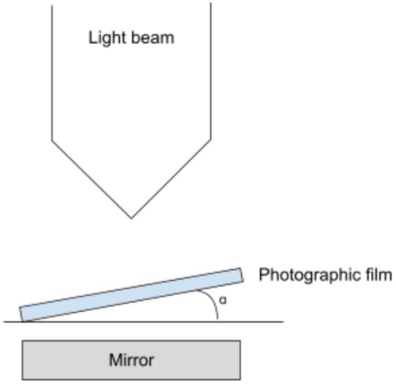
(d) In 1890, Otto Wiener performed a similar experiment but with light. Light of wavelength close to 400 nm was incident on a mirror, creating a standing wave. A piece of photographic film was placed at a small angle, $\alpha$, (approx $2^{\circ}$ ) across the path of the light as in Figure 2:
In order for Wiener to observe fringes (bands of light and dark) across his film he had to ensure that the light was monochromatic, the photosensitive film was much thinner than one wavelength and the photographic film material was not reflective.
(i) Explain briefly the relevance of these points.
(ii) Find an expression for the spacing of the fringes (dark to dark) in terms of the wavelength $\lambda$ and angle $\alpha$, and estimate the value for the experimental conditions given. (Hint: $2^{\circ}$ is approximately $1 / 30$ radian)
(e) Now consider two waves of the same amplitude but with slightly different angular frequencies, $\omega_{1}$ and $\omega_{2}$.
(i) Show that, where the waves superpose at some fixed position $x$ where the two oscillations can be written as
$$E_{z}^{1}=E_{z 0} \cos \omega_{1} t \quad \text { and } \quad E_{z}^{2}=E_{z 0} \cos \omega_{2} t$$
then the resultant wave can be written in the form: $E_{z}^{\prime \prime}=E_{z 0}^{\prime \prime} \cos \omega_{a} t \cos \omega_{b} t$
(ii) Write down the values of $E_{z 0}^{\prime \prime}, \omega_{a}$ and $\omega_{b}$
(iii) This phenomenon is known as "beats". If two light waves whose frequencies differed by 10 Hz were to superpose in this way on a screen what would be observed?
(iv) In practice the difference in two visible light frequencies might be approximately 1 MHz . If two light sources 1 MHz apart in frequency ( $f$, not $\omega$ ) are incident on a fast photodiode and the output displayed on an oscilloscope with timebase set to $0.2 \mu \mathrm{~s}$ (i.e. 1 small square on the oscilloscope corresponds to $0.2 \mu \mathrm{~s}$ ), sketch what would be seen, assuming the display is 10 squares wide.
(v) A researcher wishing to measure the frequency difference can measure on the oscilloscope to a precision of $1 / 20$ of a square using digital measuring tools built into the device. Calculate the percentage uncertainty in his measurement of the frequency difference.
(vi) Estimate a typical visible light frequency in the green part of the spectrum. To how many significant figures would the two frequencies have to be measured in order to achieve the same uncertainty in the difference between them?
It should, thus, be evident that a direct measurement of differences through interference is highly sensitive compared to measuring frequencies directly.
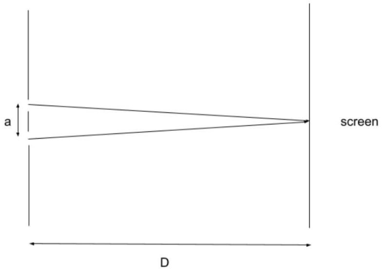
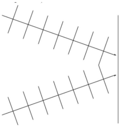
(f) Now consider the typical Young's slits arrangement. Rather than following the typical analysis, consider it to be like Wiener's experiment. The two light waves, rather than being intercepted at an angle by a film, meet at angle on a screen as in Figure 3 and produce fringes separated by a distance $y$.
(i) By considering the two beams with their wavefronts to be coming from the two slits at an angle to each other, and the wavefronts meeting at the screen (see Figure 4), find the equivalent of $\alpha$ in terms of $a$ and $D$ and write an expression for $y$. Compare it to the standard Young's slits expression.
[0pt]
(ii) Does the analogy hold perfectly? Consider the line along the middle of the slits this is always a bright point in Young's slits (i.e. where the path difference between the two beams is zero). In Wiener's experiment, when the path difference is zero (where the photographic film just touches the mirror) is a dark point. Explain. [1]
(iii) Away from the central fringe, any other bright fringe will occur where the path difference between the two rays is equal to an integer number of wavelengths. Show that the fringes lie along a hyperbola for $D \gg a$. Why is it not true for smaller values of $D$ ?
2024 Q32024Waves and Optics · Birefringence between crossed polarisers
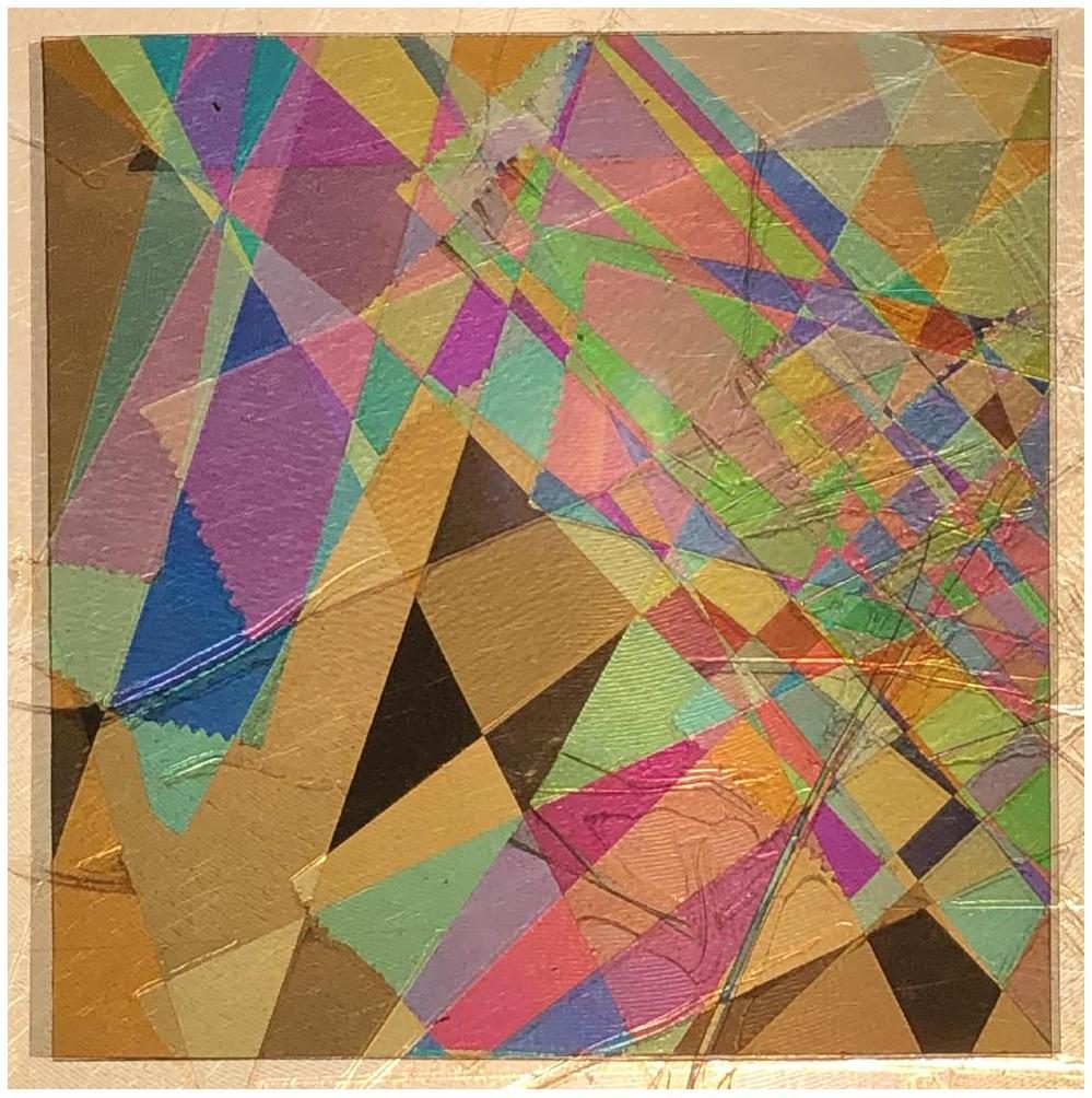
This question explores the physics of the optical phenomenon demonstrated in Figure 5.
(a) Explain why any source of light appears black when viewed through polarisation filters that are crossed, i.e., when the transmission axes of the filters are mutually perpendicular.
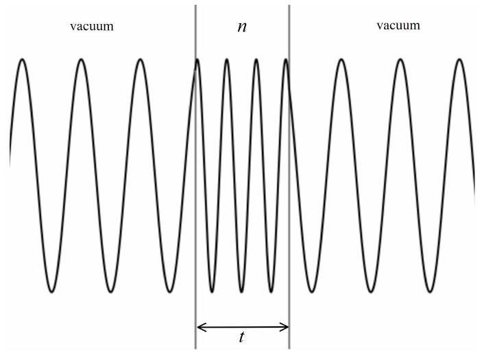
(b) Consider a transparent material of thickness $t$ and refractive index $n$, shown schematically in Figure 6. If light of vacuum wavelength $\lambda$ strikes the material at normal incidence, argue that the number of wavelengths $M$ that occupy the material is
Figure 6: Wavelength compresses when light enters an optically dense material from a vacuum.
Some optical materials display the property of birefringence. This means that the speed of propagation of light through the material depends upon the plane of polarisation of that light. Let $n_{f}$ denote the refractive index for light polarised along the 'fast' axis, and let $n_{s}$ denote the refractive index for light polarised along the 'slow' axis. These axes are mutually perpendicular and $n_{f}
(c) Assuming normal incidence, use Eq. 4 to show that the phase difference between the fast and slow waves, as they emerge from a birefringent material of thickness $t$, is given by
\begin{equation*}
\Delta \phi=\frac{2 \pi}{\lambda} t \Delta n, \tag{5}
\end{equation*}
where $\Delta n=n_{s}-n_{f}$.
The quantity $\Delta n$ is known as the birefringence of the material, and for many materials is well-modelled as a constant value across the visible spectrum. Some examples are given in the Table 1.
Table 1: Birefringence for various optical media
Material
Description
$\Delta n$
Cellotape
Sticky tape
0.0023
Cellophane
Plastic wrap
0.0110
Calcite
Mineral
0.1720
The resulting phase difference $\Delta \phi$ between the fast and slow waves can be considered to effectively rotate the plane of polarisation of incident light, in a wavelength-dependent fashion. For incident unpolarised light of intensity $I_{0}$, uniformly distributed in wavelength, it can be shown that a birefringent material sandwiched between two crossed polarisers will transmit an intensity
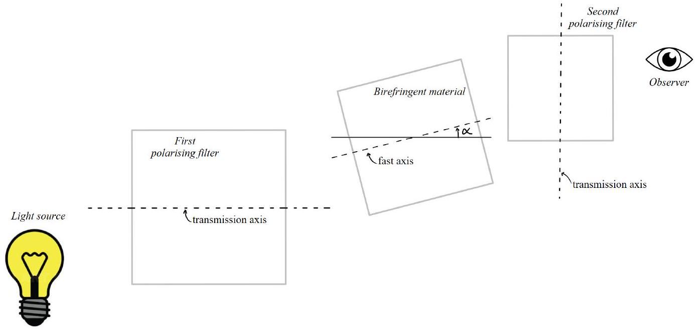
where $\Delta \phi$ is given by Eq. 5, and $\alpha$ is the angle between the fast axis of the birefringent material and the transmission axis of the first polarising filter. The experimental setup is shown schematically in Figure 7.
(d) State the angles $\alpha$ at which the fast axis of the birefringent material can be set to maximise the transmitted intensity, and explain why there is no transmission when the fast or slow axes are aligned with the transmission axis of the first polarising filter.
Figure 7: Schematic of experimental setup: a layer of birefringent material is sandwiched between two crossed polarising filters. The light source is viewed at normal incidence through this arrangement.
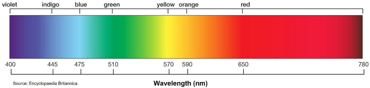
Figure 8: Visible wavelengths roughly span from 400 nm to 780 nm.
(e) Consider two crossed polarising filters sandwiching a $30 \mu \mathrm{~m}$ layer of cellophane, with its fast axis set at $45^{\circ}$ to the transmission axes of the polarising filters. Making note of Figure 8 and Table 1, sketch the transmitted intensity across all visible wavelengths. Clearly label your sketch with the letter $E$ and suggest the apparent colour of such an arrangement.
(f) Now add to the same axes another sketch, labelled $F$, showing the transmitted intensity for a $90 \mu \mathrm{~m}$ sample of cellophane (again set at $45^{\circ}$ ). Suggest the apparent colour of such an arrangement.
(g) Suppose $10 \mu \mathrm{~m}$ of an unknown birefringent material is placed between crossed polarisers. The fast axis is not aligned with the transmission axes of the polarising filters. If the transmitted light is a stark green colour, with almost no blue or red, estimate the birefringence $\Delta n$ of this material.
(h) Reason why the transmitted light appears white when a very large thickness of birefringent material is used.
(i) With reference to their manufacture, suggest why polymers such as cellotape and cellophane display birefringent properties.
(j) Suggest, experimentally, how you could determine the thickness of a sample of cellophane.
(k) Consider a crystal of calcite placed between two crossed polarisers. Estimate the minimum number of atomic layers of calcite needed to observe colourful birefringent effects. Calcite has a density of $2.71 \mathrm{~g} \mathrm{~cm}^{-3}$ and a molar mass of $100 \mathrm{~g} \mathrm{~mol}^{-1}$.