BPhO · Round 2 · Long answer

Electricity and Magnetism

12 questions — reveal the final answers. Full worked solutions: the book.

2003 Q32003Electricity and Magnetism · Thevenin equivalent circuit; current and power in a bulb

a) Figure 3.1a

figure

figure

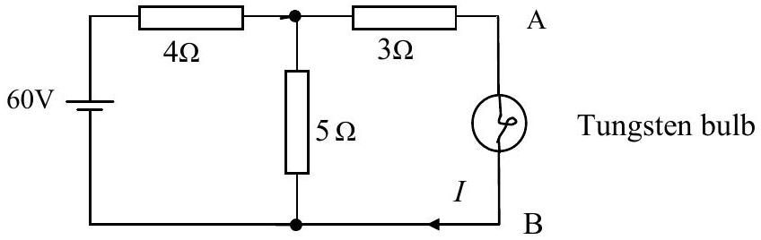
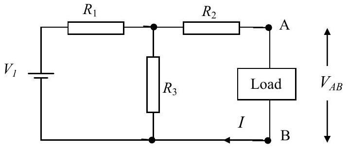
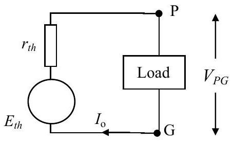
Figure 3.1a shows a circuit with three resistors, a load and one cell. Figure 3.1b shows a simplified circuit, where the three resistors have been replaced by a single resistor and the cell by a different cell. If $V_{\mathrm{AB}}=V_{\mathrm{PG}}$ and $I=I_{o}$. then show that this requires:

$$E_{t h}=\frac{V_{1} R_{3}}{R_{1}+R_{3}} \text { and } r_{t h}=R_{1}+\frac{R_{2} R_{3}}{R_{2}+R_{3}} .$$

b) Figure 3.2
figure

Figure 3.3

figure

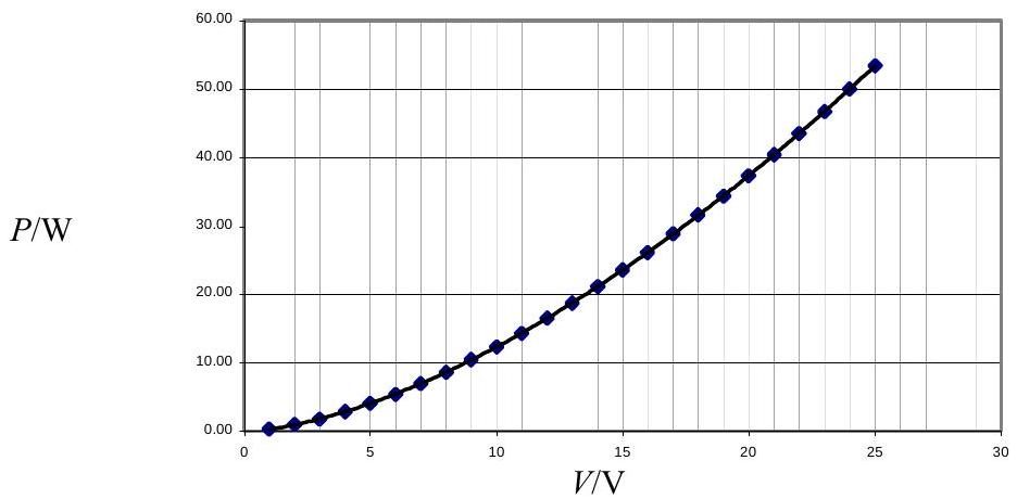
Figure 3.2 shows the power $(P) /$ P.D. $(V)$ characteristics of a nominal $24 \mathrm{~V}, 50 \mathrm{~W}$, bulb. These are the normal operating values. Figure 3.3 shows the circuit into which has been inserted. The equation of the curve in Figure 3.2 is $P=0.309 V^{1.6}$. Use an equivalent circuit (as in 3.1b) to find the current $I$ in the bulb and the power $P$ dissipated in the bulb.

If you use programmable functions on your calculator you must explain in detail your solution.
State and use simple assumptions to show that $P^{5} \propto V^{8}$ is the expected relationship for a pure tungsten filament bulb.

Show answer · 显示答案
Final answers · 最终答案
  • (a)$r_{th} = R_1 + \frac{R_2 R_3}{R_2 + R_3}$
  • (b)$P \propto \left(\frac{V^2}{P}\right)^4 \implies P^5 \propto V^8$

Full worked solutions: BPhO Round 2: Past Questions and Solutions (book)
2004 Q22004Electricity and Magnetism · Resistor networks: battery reversal, Wheatstone bridge, resistor cube

a) How do the electrical currents in the arms of a network, containing resistors and batteries, alter if the connections to all the batteries are reversed?
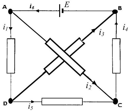
b) In Figure 2.1 all the resistors have resistance $R$ and the cell has an emf of $E$. The currents indicated in the arms are $i_{1}, i_{2}, i_{3}, i_{4}, i_{5}$, and $i_{6}$.
(i) By reversing the polarity of the battery terminals deduce, using a symmetry argument, two relationships between the currents.
(ii) Show that $i_{l},=0$.
(iii) Determine $i_{1}, i_{2}$ and $i_{6}$.

figure

Figure 2.2

c)
Figure 2.2

figure

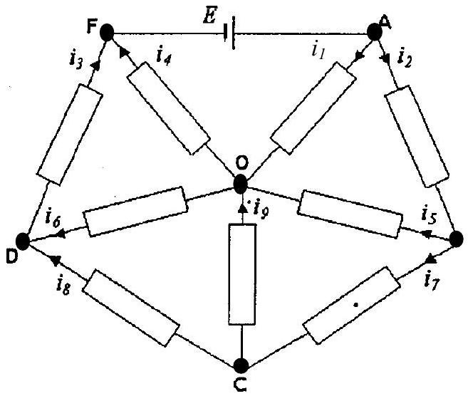
In the circuit shown in Figure 2.2, all resistors have a resistance $R$
(i) By reversing the polarity of the battery terminals deduce, with appropriate explanation, relations between the currents.
(ii) Determine a value of $i_{1}$ in terms of $E$ and $R$.
(iii) Calculate the total resistance $X$ across the cell in terms of $R$.

Show answer · 显示答案
Final answers · 最终答案
  • (a)See the book for the worked solution.
  • (b)(i)$i_2 = i_4$
  • (b)(ii)$i_5 = 0$
  • (b)(iii)$i_6 = \frac{E}{R}$
  • (c)(ii)$\lvert i_1\rvert = \frac{E}{2R}$
  • (c)(iii)$X = \frac{6R}{5}$

Full worked solutions: BPhO Round 2: Past Questions and Solutions (book)
2006 Q42006Electricity and Magnetism · Circuits: bridge balance, non-linear V-I characteristics, JFET amplifier

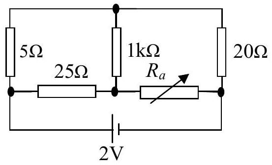
Figure 4.1

figure


a) In the circuit shown in Figure 4.1 find the value of $R_{a}$ that would give zero current in the $1 \mathrm{k} \Omega$ resistor.
b)

Figure 4.2a

figure

Figure 4.2b

figure

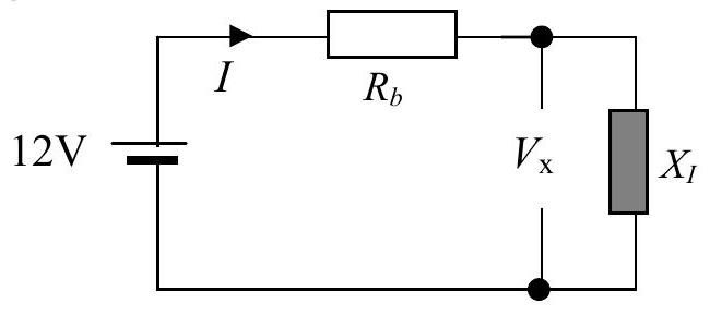
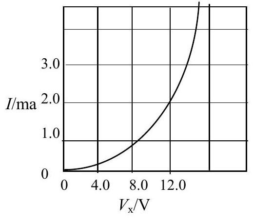
Write down an expression for $V_{x}$ in terms of the current $I$ and the resistance $R_{b}$ for the circuit in Figure 4.2a. Figure 4.2b shows the $V_{x}-I$ characteristics of $X_{I}$. In the case that $R_{b}=6.0 \mathrm{k} \Omega$ plot this expression on the graph in Figure 4.2b and deduce the value of $I$.
c) Use Figure 4.2b to obtain four values of $\delta I / \delta R_{b}$ in the range $I=0.5 \mathrm{~mA}$ to $I=1.1 \mathrm{~mA}$.

figure
figure

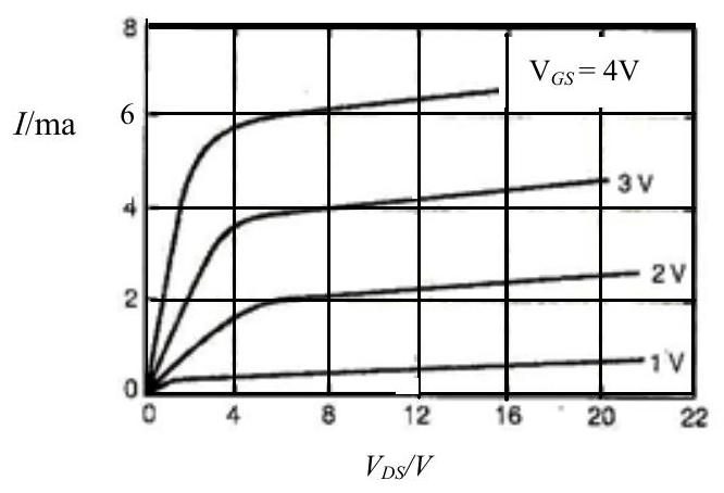
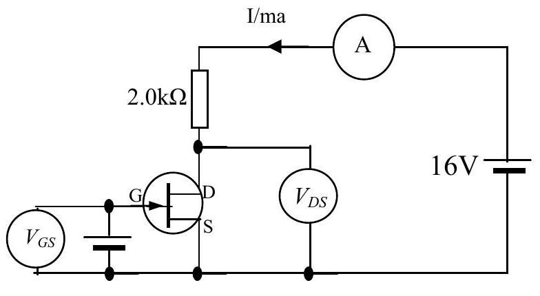
d) Fig 4.4.shows a circuit with a JFET transistor. It has three terminals D , S and G . No current flows in or out of G. The device is controlled by the electric field produced by electric potential of the gate G . Figure 4.3 shows the published characteristics of the device where the current $I$ is plotted against the p.d. $V_{D S}$ for different values of the p.d. $V_{G S}$. The circuit used for determining the characteristics does not contain the $2.0 \mathrm{k} \Omega$ resistor. Referring to the Figure 4.4 using the method of part b), or otherwise, determine:
(i) the value of $I$ when $V_{G S}$ is 2.5 V
(ii) $\frac{\delta V_{D S}}{\delta V_{G S}}$ when $V_{G S} \approx 2.5 \mathrm{~V}$. Why is this circuit found to be useful?

Show answer · 显示答案
Final answers · 最终答案
  • (a)$R_a = 0.10\ \mathrm{k}\Omega$
  • (b)$V_x=12\ \mathrm{V}-IR_b$
  • (b)$I\approx0.77\ \mathrm{mA}\ (\text{about }0.8\ \mathrm{mA})$
  • (c)$$\begin{array}{c|c|c|c} I/\mathrm{mA} & V_x/\mathrm{V} & R_b/\mathrm{k}\Omega & \delta I/\delta R_b\;\bigl(\mathrm{mA}\,(\mathrm{k}\Omega)^{-1}\bigr) \\ \hline 0.50 & 5.4 & 13.2 & -0.022 \\ 0.70 & 7.0 & 7.2 & -0.050 \\ 0.90 & 8.2 & 4.3 & -0.09 \\ 1.10 & 9.1 & 2.6 & -0.16 \end{array}$$
  • (d)(i)$I\approx3.2\ \mathrm{mA}$
  • (d)(i)$V_{DS}\approx9.6\ \mathrm{V}$
  • (d)(ii)$\frac{\delta V_{DS}}{\delta V_{GS}} = -3.6$

Full worked solutions: BPhO Round 2: Past Questions and Solutions (book)
2007 Q42007Electricity and Magnetism · Biot-Savart law and magnetic fields of wires and loops
figure

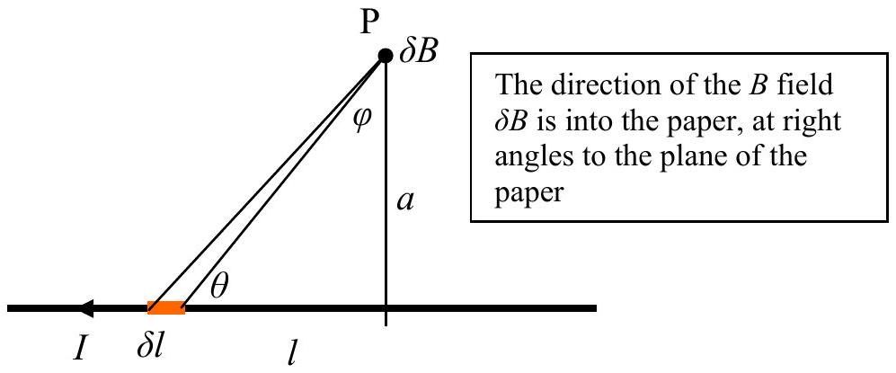
a) The Biot Savart law relates the magnetic field $\delta B$ at P to the current $I$ in an element of wire length $\delta l$ Figure 4.1.

$$\delta B=\left(\frac{\mu_{0}}{4 \pi}\right) \frac{I \operatorname{Sin} \theta \delta l}{r^{2}}$$

where $\mu_{0}$ is the permeability of free space.
b) Show that for an infinitely long wire this becomes

$$B=\left(\frac{\mu_{0}}{4 \pi}\right) \frac{2 I}{a} .$$

c)

figure

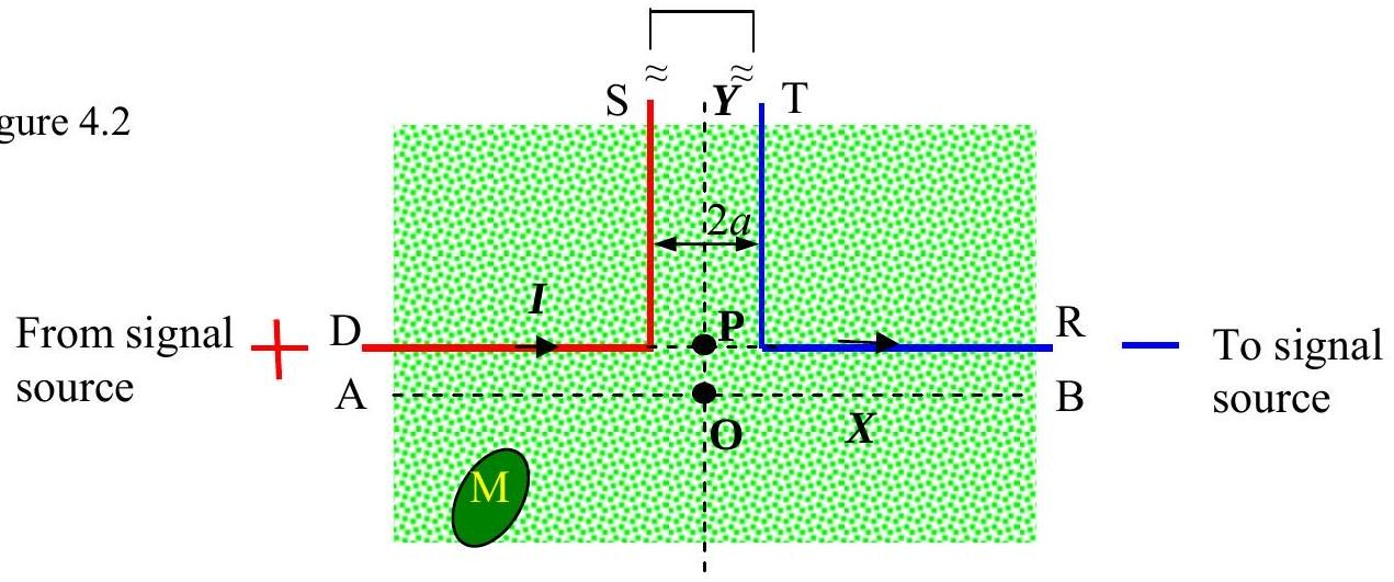
Figure 2 shows the plan view of part of a grass lawn. The mower M is controlled by the magnetic field from the wires, DS and TR, as shown in Figure 4.2. Only a small part of the lawn is shown. The wires are connected in series. The parts of the wires that are not shown in Figure 4.2 are very long. The distance PO is $a$. The blue and red wires are $2 a$ apart where they run parallel.
(i) Use the result in (b) or otherwise to find the value of the magnetic field, $B_{\mathrm{P}}$, at P .
(ii) Find an expression for the magnetic field for the magnetic field $B_{\mathrm{O}}$, at O .
(iii) Sketch the value of the magnetic field against distance along the $Y$ axis.

Show answer · 显示答案
Final answers · 最终答案
  • (a)$\sin\theta=\frac{a}{r}$
  • (b)$B=\frac{\mu_o I}{2\pi a}$
  • (c)(i)$B_{\mathrm{P}}=\frac{\mu_o I}{2\pi a}$
  • (c)(ii)$B_{\mathrm{O}} = (2-2^{1/2})B_{\mathrm{P}}$
  • (c)(iii)$B(y)=B_{\mathrm{P}} \frac{u+(1+u^2)^{1/2}-1}{u}$

Full worked solutions: BPhO Round 2: Past Questions and Solutions (book)
2008 Q32008Electricity and Magnetism · Capacitor reactance and pulse-shaping circuits

Figure 3.1

figure


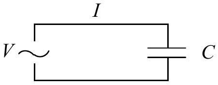
a) The charge on a capacitor, $Q$, of capacity, $C$, is related to its $\mathrm{pd}, V$, by the formula $Q=C V$. In the circuit Figure 3.1 at time $t$

$$V=V_{o} \sin \omega t,$$

$V_{o}$ is the maximum value of $V$ and $\omega$ is the angular frequency of the applied ac. Show that the current in the wires is given by

$$I=I_{o} \cos \omega t .$$

Find an expression for $V_{o}$ in terms of $I_{o}$ and $\omega$.
b) The magnitude of the impedance of the capacitor is defined as $\frac{V_{o}}{I_{o}}$.

figure
figure

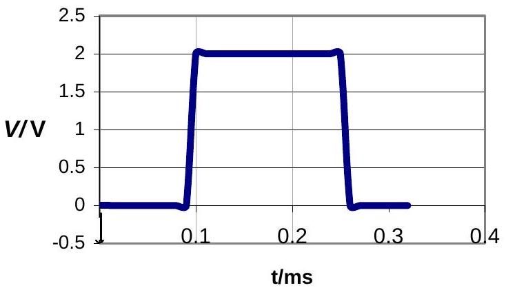
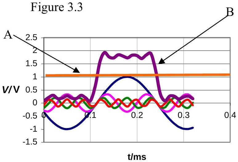
Figure 3.2 shows a periodic square pulse of 2 V with a period of 0.30 ms . This can be approximated by the addition of four sine waves and a dc of 1 V , see A in Figure 3.2. Line B , Figure 3.3, is the plot of

$$V=1+\left(\operatorname{Sin} 2 \pi f_{o} t\right)-\frac{1}{3} \operatorname{Sin}\left(2 \pi 6 f_{o} t\right)+\frac{1}{5} \operatorname{Sin}\left(2 \pi 10 f_{o} t\right)-\frac{1}{5} \operatorname{Sin}\left(2 \pi 14 f_{o} t\right) .$$

Where $f_{o}$ is the lowest frequency in Figure 3.3.
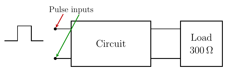
Suggest a circuit, to insert into Figure 3.4, giving suggested component value(s) such that the current in the load would be approximately a sine wave. The load has a resistance of $300 \Omega$.

Input 2 V
Pulse length 0.15 ms

Figure 3.4

figure
Show answer · 显示答案
Final answers · 最终答案
  • (a)$V_o=\frac{I_o}{\omega C}$
  • (a)$\frac{V_o}{I_o}=\frac{1}{\omega C}$
  • (b)$L=0.10\ \mathrm{H}$
  • (b)$C\approx2.3\times10^{-8}\ \mathrm{F}$
  • (b)$\text{in series with the load}$

Full worked solutions: BPhO Round 2: Past Questions and Solutions (book)
2011 Q22011Electricity and Magnetism · Biot-Savart field of a wire; toroidal pick-up coil; grid voltage

Q2
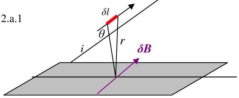
(a) Figure 2.a. 1

figure

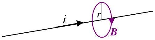
The law of Biot-Savart states that if a current $i$ is flowing in a wire at an angle $\theta$ to a plane then the magnetic flux density $\delta B$, as shown, is given by:

$$\delta B=\frac{\mu_{0} i \delta l \sin \theta}{4 \pi r^{2}}$$

See Figure 2.a.1.

Hence show that a current $i$ flowing through a single straight very long wire will cause a field of $B=\frac{\mu_{0} i}{2 \pi r}$ as shown in Figure 2.a.2.

figure

(b) Figure 2.b. 1

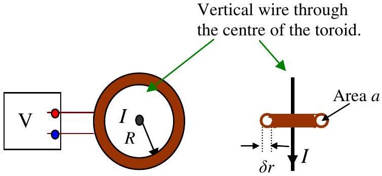
figure

A copper wire carrying a current of $I$ is shown in Figure 2.b.1. A toroidal coil, radius $R$, wound with copper wire carries a current $I$. The toroid has $N$ turns of wire and the cross sectional area of the ring is $a$, diameter $\delta r$. If the current in the vertical wire changes at a rate of $\frac{d I}{d t}$, what will the voltmeter read? (Assume $\delta r \ll R$ ).
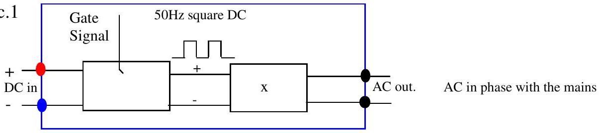
(c) A device called an inverter can be use to change DC into AC. A "tied" inverter connects a DC supply to the 240 V 50 Hz mains so that the p.d. produced by the inverter is sinusoidal and in phase with the mains. An example of the use of an inverter is to enable a photovoltaic panel to supply power to the grid. A block diagram of the type of circuit that could be used in an inverter is illustrated in Figure 2.c.1.

Figure. 2.c. 1

figure

The steady DC is interrupted by the gate signal that produces an interrupted DC signal in phase with the mains. Suggest components that should be inserted in the box $(\mathrm{x})$ to make the output sinusoidal and justify this choice by numerical calculations if appropriate.

Show answer · 显示答案
Final answers · 最终答案
  • (a)$B=\frac{\mu_0 I}{2\pi R}$
  • (b)$|V|=\frac{\mu_0Na}{2\pi R}\left|\frac{dI}{dt}\right|\ \mathrm{V}$
  • (c)$\frac{N_{\mathrm{s}}}{N_{\mathrm{p}}}=\frac{240}{V_{\mathrm{p}}}$

Full worked solutions: BPhO Round 2: Past Questions and Solutions (book)
2012 Q42012Electricity and Magnetism · The memristor and magnetic dipoles; Hall probe mapping

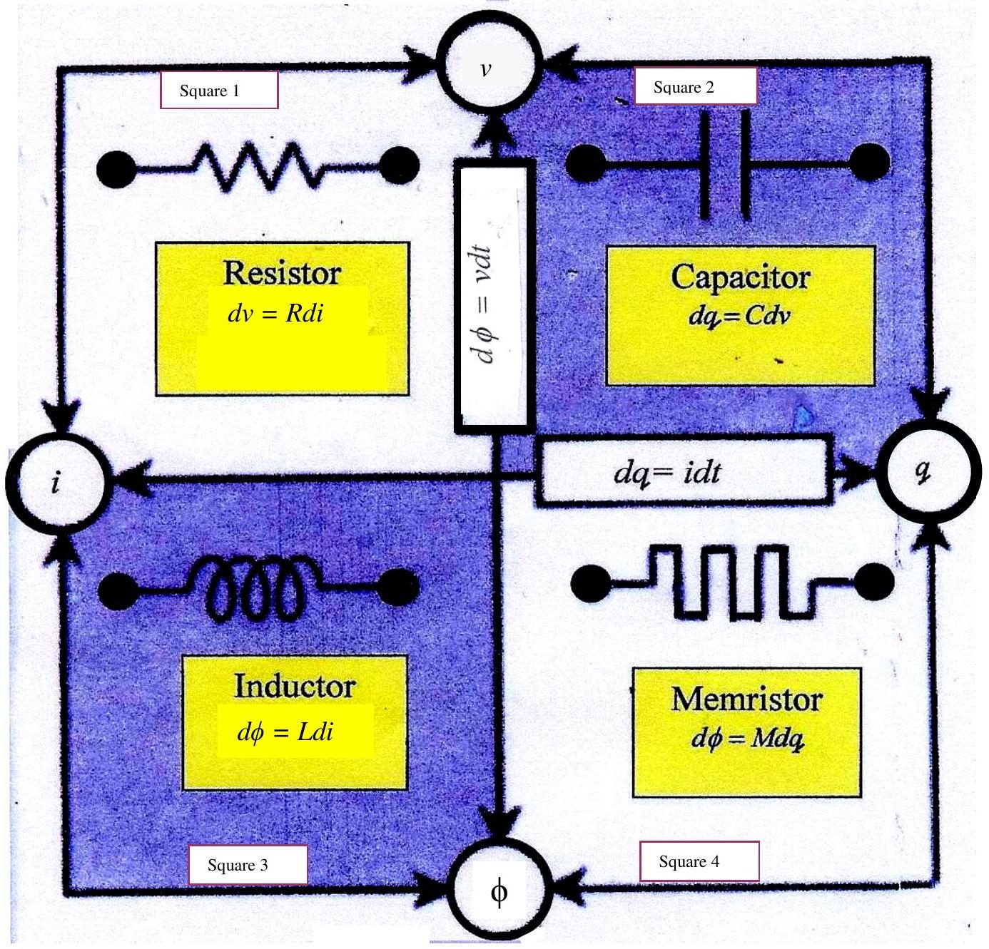
(a) In 1971 Leon Chua formulated the theory of the memristor. It is a passive two terminal device. He realised that he could relate the circles labelled $v, q, i, \phi$ diagrammatically, as shown in Figure 4.1. Figure 4.1 is not a circuit diagram. The resistor in square 1 relates $v$ and $i$. The capacitor in square 2 relates $q$ and $v$. The inductor in square 3 relates $\phi$ and $i$. However, a device seems to be needed in square 4 to complete the symmetry. The name memristor was suggested for this device. In April 2008 HP Labs announced the development of a switching semiconductor memristor.

figure

(i) Are the equations in Figure.4.1 dimensionally consistent?
(ii) The team that first produced a memristor on a chip suggested that it could revolutionise the fabrication and use of computer memories. How?

figure

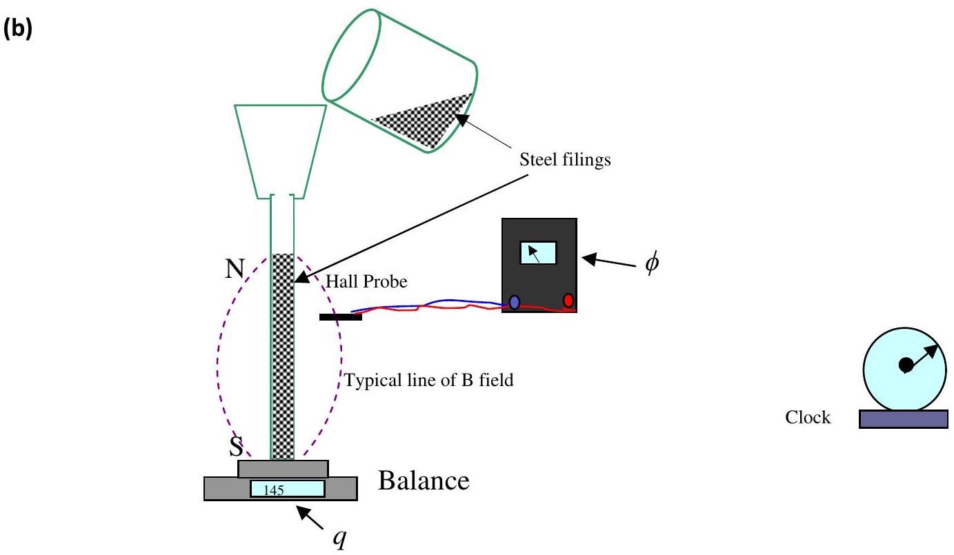
A student has been given the task of making a practical analogue of a memristor. She thinks that she could make a bar magnet from lightly magnetised steel filings covered in a thin layer of slippery plastic placed in a suitable tube. Explain how this set up is an analogue of a memristor. Her idea is illustrated in Figure 4.2. Comment briefly on the suggested analogue, being careful to explain the physics involved.
(c)

figure
figure

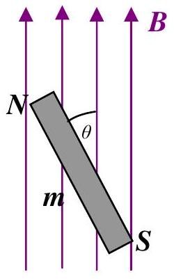
(i) A magnet will set itself along the field lines if it is able to rotate in the plane of the paper (Figures 4.3). There is a torque on the magnet due to the magnet's interaction with the Earth's field. The magnetic moment of a magnet, $m$ is the maximum torque on it in a field of 1 T . Find an expression for the torque on the magnet illustrated in Figure 4.3.
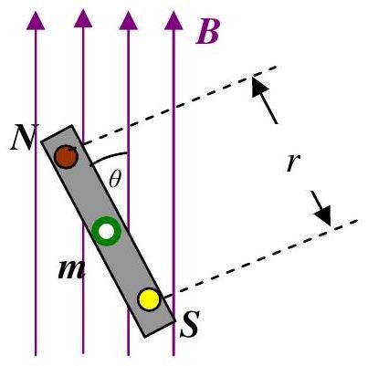
(ii) It is possible to imagine a model of a magnet as a dipole where the pole strength is $q_{m}$. See Figure. 4.4. The poles are $r$ apart. The force between two isolated magnetic poles is similar to that between two isolated charges i.e. where $\mu$ is the magnetic permeability of the intervening medium.

$$F=\frac{\mu q_{m 1} q_{m 2}}{4 \pi r^{2}}$$

What is the relationship between $q_{m}$ and $m$ ?

figure

(i) Figure 4.5 illustrates two "isolated" magnetic poles. The other two poles can be regarded as too far away to interact or contribute to the field. How can you find the direction of the field lines using a Hall probe?
(ii) Show that for a small isolated magnet, the magnetic field $B$ at a large distance away $d$ from the magnet will be proportional to $\frac{1}{d^{3}}$.

Show answer · 显示答案
Final answers · 最终答案
  • (a)(i)$[M] = \Omega$
  • (a)(ii)$v=M(q)i$
  • (b)$M_{\text{analogue}}=\frac{d\phi}{dq}$
  • (c)(i)$\tau=mB\sin\theta$
  • (c)(ii)Thus $q_m$ has units $\mathrm{A\,m}$ and $m$ has units $\mathrm{A\,m^2}$.
  • (d)(i)See the book for the worked solution.
  • (d)(ii)$B = \frac{\mu m}{2\pi d^3} \propto\frac{1}{d^3}$

Full worked solutions: BPhO Round 2: Past Questions and Solutions (book)
2012 Q52012Electricity and Magnetism · Hall effect: drift velocity and Hall voltage

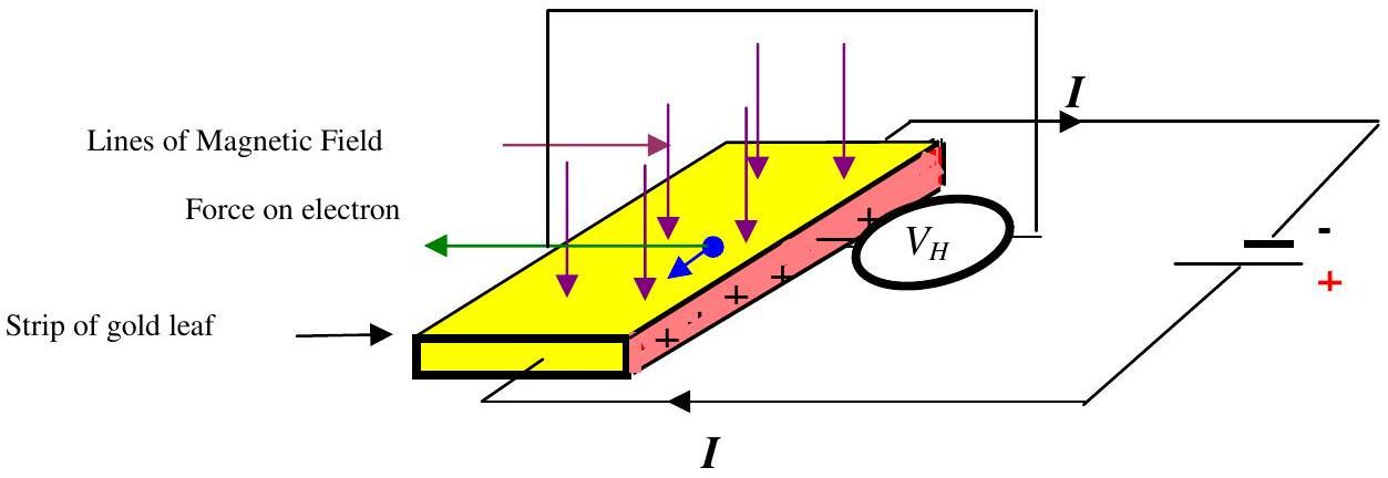
In the late $19{ }^{\text {th }}$ century the American student, Edwin Hall, was given the problem of observing the effect of a magnetic field on electrons travelling in a conductor. This is known as the Hall effect and the probe has been used in Q4.

figure

Figure 5.1. Illustrates the experiment. A current is passed through a strip of gold leaf and the current carriers (usually electrons) pass through the gold leaf. The current passes through the gold leaf in the direction shown. The magnetic field acts on the moving current carriers and these carriers are pulled to the left. One thin edge of the gold leaf becomes positive (coloured pink/grey), relative to the other side. The Hall voltage, $V_{H}$ is the p.d. between points on the pink/grey face and the side opposite.
(i) The number density of the carriers is $n$, the cross sectional area of the strip is $a$, the charge on the current carrier (electrons) is $e$. Derive or write down an expression for the drift velocity, $v_{d}$ in terms of $I, n, a, e$.
(ii) Draw a circuit diagram that shows a practical circuit that could measure the Hall effect in a strip of gold leaf. The effect is very small.
(iii) The charge carriers in semiconductors are fewer - therefore they move more rapidly for the same current density. How does this make the sensors based on Hall voltage more sensitive? In some materials the polarity of the voltage is reversed. Comment.
(iv) Measuring the thickness of the gold leaf is difficult. A student knows that when viewing a strong white light through a piece of gold leaf the light appears green - blue. He has also read that if 1 g of gold is beaten out as thin as possible it covers an area of $50 \mathrm{~m}^{2}$. Are these facts consistent? Explain.
(v) The highest field available is 0.1 T . The length of the gold leaf is 40 mm , the width 10 mm and the current is 200 mA . What is the drift velocity of the free electrons (one per atom)? What would be the Hall voltage?

Show answer · 显示答案
Final answers · 最终答案
  • (i)$v_d=\frac{I}{na|e|}$
  • (ii)$V_H=\frac{V(+B)-V(-B)}{2}$
  • (iii)$V_H = \frac{IB}{n|e|t}$
  • (iv)$t = 1.04\times10^{-9}\text{ m}$
  • (v)$V_H = 2.03\text{ mV}$

Full worked solutions: BPhO Round 2: Past Questions and Solutions (book)
2013 Q32013Electricity and Magnetism · Eddy-current retarder on a copper disc

Most heavy vehicles are equipped with retarders that have a copper disc on a rotating axle. An electromagnet produces a magnetic field and this produces a force on the moving disc.

figure

The gradient of the road is $20 \%$ (take this as the height lost/distance gone). The truck has a mass of 10 tonnes. The diameter of the copper disc is 0.5 m , the thickness of the disc 15 mm . Ignore other forms of braking such as engine braking, normal disc brakes, air resistance, etc.
(i) Find an expression that would give the rate of heat generated in the copper disc.
(ii) Find the initial rate of rise of temperature of the copper disc. The electromagnetic braking is designed to allow the lorry to descend a slope of $20 \%$ at a steady $5 \mathrm{~ms}^{-1}$ without using engine braking or normal friction brakes.
(iii) Estimate the final temperature of the disc assuming that the heat is lost only through radiation. Stefan's law states that the power radiated by a black body is $\mathrm{A} \sigma T^{4}$ where A is the area of the radiating body and $\sigma$ is the Stefan-Boltzmann constant. You may assume that the disc approximates to a black body in this case.

Show answer · 显示答案
Final answers · 最终答案
  • (i)$\frac{dT}{dt} = \frac{Mv\left(g\sin\theta-a\right)}{m_{d}c}$
  • (ii)$\frac{dT}{dt}\cong 10.3\ \mathrm{K\,s}^{-1}$
  • (iii)$T\approx1428\,\mathrm{K}\quad\text{(both faces and rim)}$ Corrected — the printed 1712 K uses an incorrect slope and radiating area; see the interactive walkthrough.

Full worked solutions: BPhO Round 2: Past Questions and Solutions (book)
2014 Q22014Electricity and Magnetism · Fourier square waves, solar-cell power transfer, transmission lines, flywheels

It can be shown that a square wave can be represented by a sum of sine waves as given by the formula below

$$v=v_{0} \sin \omega_{0} t+v_{1} \sin \omega_{1} t+v_{2} \sin \omega_{2} t+v_{3} \sin \omega_{3} t+\ldots .$$

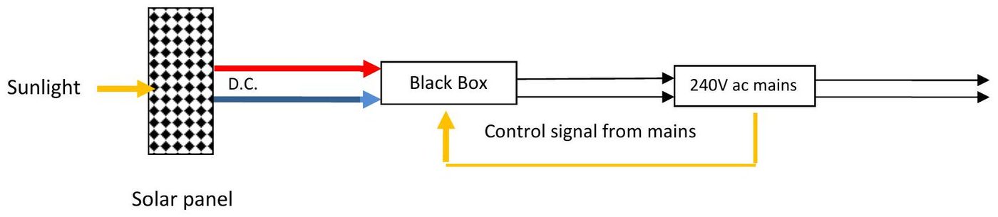
Solar cells have an output that is dc. The pd across a cell depends on the incident radiation and the efficiency of the solar cells - Hubble telescope cells have an efficiency of about $30 \%$ in full sunlight. Solar cells for use on buildings etc. normally have an efficiency of about $15 \%$. The dc power from the solar cells has to be transmitted to the mains which is 240 V ac. At your disposal you have electronic black boxes. A possible solution is sketched out in Figure 2.1 below.

figure

What is the black box for? Suggest components for the black box.

Some electrical energy may be lost as heat. How can you maximise the efficiency of the electrical energy transfer from the solar panels to the 240 V ac of the mains?

Explain why electrical energy is transferred by the grid using three or four wires.
It has been suggested that one way of storing electrical energy would be to store it in a rotating flywheel. A simple flywheel should store electrical energy from a 1 MW power supply for 20 minutes. Suggest a design for this flywheel. Marks are awarded for the detail of the design.

Show answer · 显示答案
Final answers · 最终答案
  • (a)The panel voltage must therefore be raised to a dc link voltage above about $340\text{ V}$, using a switched-mode boost converter or a transformer.
  • (b)$P_{\mathrm{loss}} = \frac{P^{2}R}{V^{2}}$
  • (c)A fourth, neutral, wire is provided where single-phase loads are connected or the three phase currents may be unequal; it carries the imbalance current and provides the phase-to-neutral voltage of $240\text{ V}$.
  • (d)Its hoop stress is of order $\rho_{\mathrm{steel}}v_{\mathrm{rim}}^{2}=3.1\times10^{8}\text{ Pa}$, so high-strength material, a large safety factor and a massive containment vessel are essential.

Full worked solutions: BPhO Round 2: Past Questions and Solutions (book)
2015 Q42015Electricity and Magnetism · Magnetic rifle: solenoid forces and induction

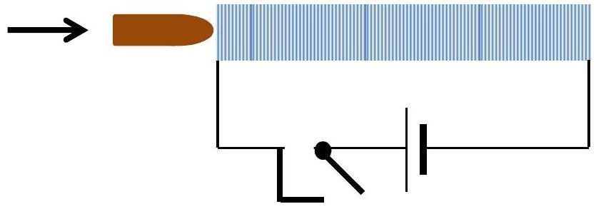
Figure 3a shows simplified design working of a magnetic rifle. The bullet is made of a magnetic material such as iron. The idea is that the trigger switches on the current, this draws the bullet into the solenoid and the bullet proceeds on its way. However trials showed that it did not work. Why do think this was so? Suggest modifications and explain as numerically as you can how your modifications would work.

figure
Show answer · 显示答案
Final answers · 最终答案
  • Final result$v=3.2\text{ m s}^{-1}$

Full worked solutions: BPhO Round 2: Past Questions and Solutions (book)
2017 Q22017Electricity and Magnetism · Giant magnetoresistance in layered ferromagnets

Magnetic properties of electrons are intrinsically related to their spin. In ferromagnetic materials, unpaired electron spins line up with each other within regions called domains. Within domains the magnetic field is therefore intense, though domains will generally be randomly orientated with respect to one another so that a bulk sample will usually be unmagnetised. However, an externally applied magnetic field can cause the magnetic domains to line up with each other; the material is said to be magnetised.

Electrons, although point particles, behave as if they were spinning and act like tiny magnets. Electrons in a ferromagnet whose spins are oriented in the direction of (parallel), or opposite to (antiparallel), the internal magnetisation carry independent currents, leading to the material behaving as if it has different resistivities $\rho_{\mathrm{p}}$ and $\rho_{\mathrm{a}}$ for each of the two current components.

Two ferromagnetic layers with identical dimensions (length $\ell$, cross-sectional area $A$ ) but opposite magnetisation are placed next to each other in parallel with a cell of e.m.f. $\varepsilon$ and internal resistance $r$. The resistance of the rest of the external circuit is modelled by a resistance $R$ in series with the ferromagnetic layers.
(a) Draw a diagram of the circuit described above.
(b) Find the total resistance of the circuit.
(c) An external magnetic field is now applied to the ferromagnetic layers causing their magnetisation to line up. Draw a new circuit diagram and find the total resistance in this case.
(d) The current component parallel flows much more easily than that antiparallel, meaning that $\rho_{\mathrm{p}} \ll \rho_{\mathrm{a}}$.
(i) Find an expression for the change in current between the two situations before and after the external field is applied.
(ii) For fixed resistances (and fixed resistivities $\rho_{\mathrm{p}} \ll \rho_{\mathrm{a}}$ ), under what conditions is the change in current maximised?
(e) The effect described above is known as magnetoresistance, and can be employed in the construction of hard disk read/write heads. Suggest how one of these might work and how the result of (d) (ii) is relevant. What other considerations are there?

Show answer · 显示答案
Final answers · 最终答案
  • (a)See the book for the worked solution.
  • (b)$R_{\mathrm{off}} = R+r+\frac{\ell}{2A}\left(\rho_{\mathrm p}+\rho_{\mathrm a}\right)$
  • (c)$R_{\mathrm{on}}=R+r+\frac{2x\rho_{\mathrm p}\rho_{\mathrm a}}{\rho_{\mathrm p}+\rho_{\mathrm a}}$
  • (d)(i)$\Delta I=\varepsilon\left(\frac{1}{2x\rho_{\mathrm p}+R'} -\frac{1}{x\rho_{\mathrm a}/2+R'}\right)$
  • (d)(ii)$\frac{\ell}{A} = \frac{R+r}{\sqrt{\rho_{\mathrm p}\rho_{\mathrm a}}}$
  • (e)See the book for the worked solution.

Full worked solutions: BPhO Round 2: Past Questions and Solutions (book)