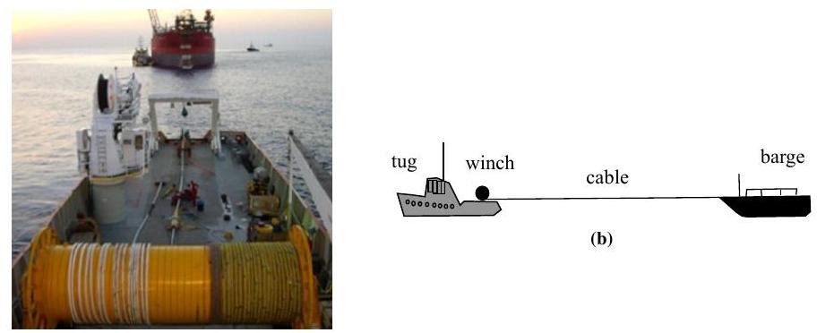
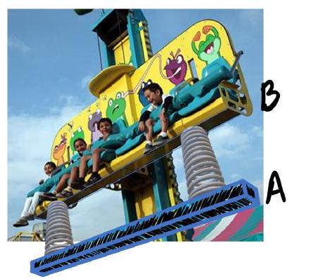
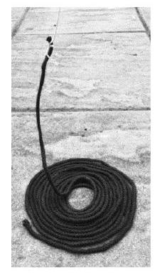
A tug boat winch is fitted with friction brakes that slip when the tension in the winch cable reaches $50 \mathrm{kN}$. The winch is mounted on a 450 tonne tug which is to tow a floating barge of mass 6300 tonne. The barge is initially at rest while the tug moves away from it at. The speed of the tug at the moment that the cable becomes taut is $2.5 \mathrm{~m} \mathrm{~s}^{-1}$. At that moment the winch friction brakes start slipping in order to prevent the cable from breaking. The thrust exerted on the tug by its propeller is $35 \mathrm{kN}$. The winch and arrangement might look something like Figure 1:
(a) The winch can be seen in the lower part of the picture. Photo: Casey Ocean Systems
Figure 1
a) [9] Calculate
(i) The time during which the brakes are slipping,
(ii) The common velocity of the tug and the barge when the brakes stop slipping.
(iii) What length of cable runs out of the drum of the winch during the time the brakes are slipping?
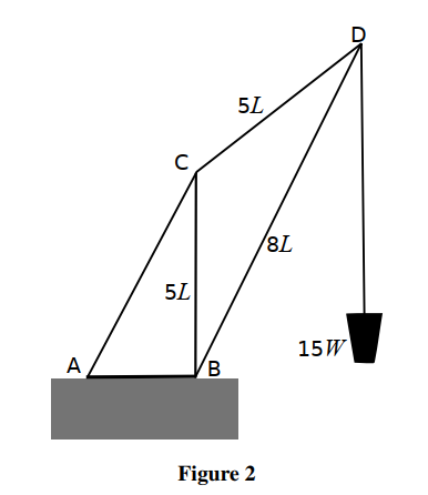
b) [8] In a different geometry the winch is used to haul sand up from the bottom of a dry dock using a crane constructed from a very light framework of girders. The crane geometry can be seen in the diagram of Figure 2 . The crane is fixed to the horizontal dock side at points $A$ and $\mathrm{B}$. The dimensions of the sides $C B, C D$ and BD are as shown, the girder CB is vertical, and the winch is hauling a load of weight $15 W$.
(i) Find the magnitude of the force exerted on $D$ by the member BD,
(ii) The tension in the member CD.
(iii) If the force on the crane at $A$ by the ground acts vertically downwards and
has a magnitude $31 W$, find the distance AB in terms of $L$.
c) [8] The bucket of mass $m$ is drawn up by the winch cable which exerts a steady force $F$ upwards, shown in Figure 3. The bucket starts from rest and initially contains a mass $m_{0}$ of sand. The sand leaks out at a constant rate so that the bucket is empty after time $t$, which occurs before it reaches the top of the dry dock wall.
In terms of $F, m_{0}, m, t$ and $g$ (the gravitational field strength), what is the velocity $v$ of the bucket when it is just empty? The friction brakes do not slip.
a) [5] A particle is moving in a horizontal circle and is kept in its path by a string tied to a point at a height $h$ above the centre of the circle.
(i) Find the period of rotation in terms of $h$ and the gravitational field strength $g$, explaining the physics of your derivation in words.
(ii) If the tension in the string is three times the weight of the particle, find the length of the string $\ell$, in terms of $h$.
b) [7] (i) A particle of mass $m$ is suspended by a thin elastic string of natural length $a$ in which a tension $m g$ would produce an extension $a$. Write down an expression for the period of oscillation of the mass in terms of $a$ and $g$.
(ii) Two particles of equal mass $m$ on a smooth horizontal table are connected by the same thin elastic string of natural length $a$. The particles are held at rest at a distance $3 a$ apart.
i. Describe their motions between the time they are released and when they collide.
ii. If the particles are released simultaneously, calculate the time elapsed before they collide, given $a=0.20 \mathrm{~m}$.
c) [5] A piece of elastic cord of length $\ell$ and cross-sectional area $A$ is stretched to twice its natural length. Assuming that the total volume remains constant, and that cross-sectional area is uniform along its length, and the Young's modulus $E$ for the material remains constant,
(i) obtain an expression for the final tension in terms of $E$ and $A$.
(ii) Show that the work done in stretching the elastic is given by $E \ell A(1-\ln 2)$.
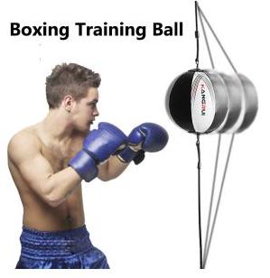
d) [8] The behaviour of the boxing training ball shown in Figure 2 can be modelled as two identical vertical springs attached to a mass, $m$. The springs each have a natural length $\ell$, and a spring constant $k$, such that an applied force of $m g$ doubles the length of spring to $2 \ell$. The top and bottom springs are attached to the ceiling and floor respectively in a room of height $4 \ell$.
Assume the radius of the ball, $r \ll \ell$.
(i) Determine the equilibrium position of the ball below the ceiling in terms of $\ell$.
(ii) The ball is given a small vertical displacement and released. Find an expression for the period $T_{\mathrm{v}}$ for the vertical oscillations.
(iii) The ball is given a small horizontal displacement. Using a suitable approximation provide an expression for the horizontal force $F_{\mathrm{h}}$ exerted on the ball by the springs.
(iv) Find an expression for the period of the horizontal oscillations $T_{\mathrm{h}}$ and evaluate the ratio $T_{\mathrm{h}} / T_{\mathrm{v}}$.
Several mechanical fairground rides are analysed in this question.
a) [2] A particle of mass $m$ moves at a constant rate in a horizontal circular path of radius $r$. State why there must be a resultant force acting on the particle; indicate its direction on a diagram, and state its magnitude both in terms of its speed $v$ and its angular speed $\omega$
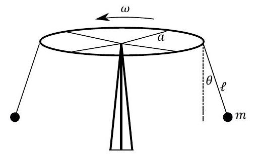
b) [2] A fairground ride consists of a set of chairs hanging from cables of length $\ell=4.0 \mathrm{~m}$, which are attached to circular support of radius $a=6.0 \mathrm{~m}$, as shown in Figure 4 below. Each passenger sits in a light chair, with combined mass $m$, which can be treated as a point mass at the end of each cable. The ride rotates at angular speed $\omega$, and the cable hangs at an angle of $\theta=30^{\circ}$ to the vertical.
Obtain an expression for the angular velocity $\omega$ in terms of $\ell, a, \theta$ and $g$ and then evaluate $\omega$ for the given values.
Figure 4
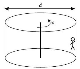
c) [6] The "wall of death" ride consists of a $d=10 \mathrm{~m}$ diameter drum which rotates at an angular rate $\omega$, shown in Figure 5a. Passengers stand against the inside vertical, rough wall and as the ride speeds up to rate $\omega$, they are held against the wall and cannot slide down due to friction with the wall.
(a)
(b)
Figure 5 (i) Sketch a diagram of the three forces acting on a passenger who is held against the wall.
(ii) If the frictional force is given by $f=\mu N$ where $N$ is the normal reaction force of the wall, and $\mu=0.4$, calculate the minimum value of $\omega$ for the drum in order for passengers to be held against the wall.
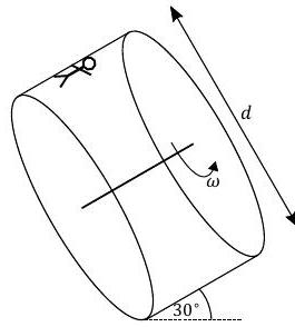
(iii) The rotating drum is now tilted through $60^{\circ}$ so that its axis of rotation is $\theta=30^{\circ}$ above the horizontal (Figure 5b). Sketch a diagram of the three forces acting on a passenger when they are at the highest point of the circular path.
(iv) The frictional force $f$ remains as $\mu N$ with $\mu=0.4$ although the value of $f$ will be different as the wall is no longer vertical. Given this condition on $f$, calculate the new value of the minimum angular velocity, $\omega_{t}$ of the drum so that passengers are held against the wall at the highest point.
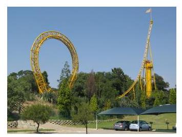
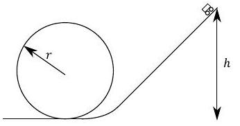
d) [8] Roller coasters operate using gravity and are not powered. A roller coaster similar to that illustrated in Fig. 6 can be modelled as a circular loop of radius of $20 \mathrm{~m}$ connected to a straight sloping track, shown in Figure $7 .$
(i) Now use the simplified model of Figure 7. Estimate the minimum height $h$ of the top of the slope from which a car must start in order to remain in contact with the track at all times when the car travels around the loop of radius $r=20 \mathrm{~m}$ without falling. Friction can be neglected.
Hint: consider the forces acting on the car at the top of the loop, and the minimum speed needed to remain in contact.
Figure 7
(ii) In this simplified model of the loop ride, the straight track joins on to the circular track at the bottom of the slope. Friction now acts on the carriage such that the frictional force is $f=\mu N$, where $N$ is the normal contact force of the track on the carriage and $\mu=0.05$. i. Draw a force diagram for the resultant force acting on the carriage as it accelerates down the straight track.
ii. For a track length $\ell=60 \mathrm{~m}$ at an angle $\theta=40^{\circ}$ above the horizontal, by what percentage does friction reduce the speed of the carriage at the bottom of the sloped track?
(iii) We again neglect friction. The straight track now joins a curved track with a radius of curvature of $\ell / 2$. What would be the change in the normal contact force acting on a $60 \mathrm{~kg}$ passenger from his seat at the moment the carriage enters the curve?
e) [7] A student has an even more unusual idea for a fun-fair ride. This can be modelled as two bars (A and $\mathbf{B}$ ) each of mass $M$ separated by two springs of negligible mass, each of spring constant $k$ and unstretched length $\ell$. The springs are lightly damped to stop vibrations. This is similar to the example shown in Figure 8. The lower bar $\mathbf{A}$ is initially at a height of $h$ above the ground. The ride is then released from rest and falls freely under gravity.
(i) Find an expression for the speed of the bars immediately before they hit the ground.
(ii) Bar A strikes the ground and is brought to rest almost instantaneously, its kinetic energy all being transferred to heat and sound. Determine the total energy of the system, $E$, in terms of the subsequent maximum compression of the springs $x_{m}$, and gravitational potential energy.
After this, the springs extend again, and then at some moment bar $\mathbf{A}$ lifts off the ground.
(iii) By considering the forces acting on $\mathbf{A}$ determine the extension $x_{e}$, of the springs at the instant A leaves the ground.
(iv) Hence, using energy considerations, deduce an expression for the condition the initial height $h$ must satisfy in order for $\mathbf{A}$ to leave the ground.
This question is about dynamics in nautical examples.
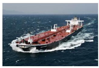
a) [8] An oil tanker as illustrated in Figure $\mathbf{2 a}$ will typically have a length of $272 \mathrm{~m}$, a breadth of $48 \mathrm{~m}$ and a height from the bottom of the ship to the deck surface of $24 \mathrm{~m}$. The mass of the ship alone is 22000 tonnes. A typical full load would be 158000 tonnes of crude oil with a density of $900 \mathrm{~kg} \mathrm{~m}^{-3}$.
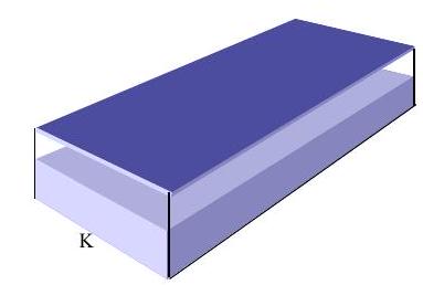
We model the tanker as a closed cuboid tank carrying oil at the bottom, of uniform crosssection, as shown in Figure 2b.
(i) Calculate the distance from the water line to the deck when the tanker is loaded with a full tank that occupies the lower part of the ship as shown in Figure $2 \mathbf{b}$. Take the density of sea water to be $1025 \mathrm{~kg} \mathrm{~m}^{-3}$.
(ii) Calculate the height of the centre of mass of the loaded ship above the base centre point, K, shown in Figure $\mathbf{2 b}$.
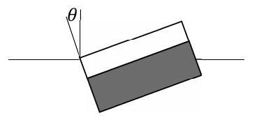
(iii) The ship lists to one side to the point where water just reaches the deck, as illustrated in Figure 3. Calculate the angle to the vertical $\theta$, where $\theta$ is a small angle. (The buoyancy force acts at the centre of mass of the displaced water.)
Figure 3: When the ships tilts, we assume the oil remains stationary inside due to internal baffles and walls
(iv) Determine the resultant turning moment acting on the ship.
b) [6] A capstan (a rotating cylinder) on the ship pulls up a uniform heavy chain from the dockside by means of a much lighter thin rope of negligible mass, as in the photograph in Figure $4 .$
(i) The chain is pulled up from the ground at a constant speed $v$. It has a mass per unit length of $\lambda$. If the length of heavy chain lifted from the ground and suspended from the rope is taken to be $x$, find expressions for the force, $F$, and the power, $P$, supplied by the ship's capstan in terms of $x, \lambda, v$ and $g$.
(ii) Find an expression for the upward contact force $R$ from the dockside, acting on the chain whilst it is being pulled up, taking the total length of chain to be $L$.
Figure 4
c) [5] The heavy chain, with an effective cross-sectional area of $A$, stretches under its own weight. Find an expression for the extension of the chain $e$, as a function of its suspended length $x$. The heavy chain has a mass per unit length $\mu$, a Young's modulus of $E$, and the gravitational field strength is $g$. The cross-sectional area of the chain is assumed to remain constant.
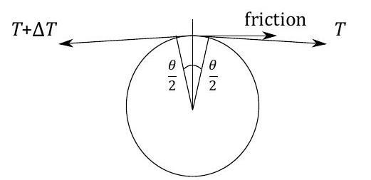
d) [6] A strong rope can be used to pull on a large ship by wrapping the rope around a capstan (a cylinder) and holding the loose end of the rope with a small force. The friction of the rope on the capstan acts as a force multiplier. If a rope is in contact with a cylinder with friction acting, as shown in Figure 5, in which the angle $\theta$ is small.
(i) Sketch a fully labelled diagram to show the normal component of the tension acting on the capstan from the rope.
(ii) Obtain an expression relating the tension in the rope $T, \Delta T, \theta$ and the coefficient of friction $\mu$.
The coefficient of friction is given by; frictional force $=\mu \times$ normal reaction force of the capstan.
(iii) By integrating your result relating $\Delta T$ and $T$, obtain the relation between the tensions on the ends of the rope for large angles $\theta$.
(iv) Approximately how many turns of a rope on a capstan for which the coefficient of friction $\mu=0.3$ would be required if you were to balance a person's weight of $\approx 600 \mathrm{~N}$ with a weight equivalent to the "weight of the Earth" $\left(6 \times 10^{25} \mathrm{~N}\right)$ ?
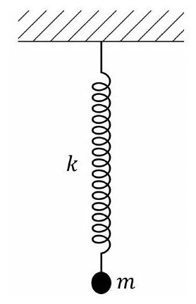
a) (i) [2] A vertical spring of unstretched length $\ell_{0}$ and spring constant $k$ is fixed to a rigid support, as in Fig. 15. A mass $m$ is attached and the equilibrium length is then $\ell$.
i. The mass is displaced by a small distance $x$ downwards from its equilibrium position. Draw a diagram of the mass and mark on the forces acting.
ii. Referring to your forces diagram, show that the period of oscillation is given by
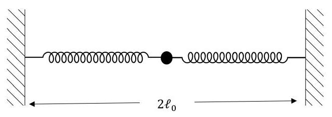
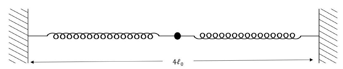
(ii) [2] Two identical springs each of unstretched length $\ell_{0}$ are attached to walls a distance $2 \ell_{0}$ apart, and attached at the centre to a mass $m$, as shown in Fig. 16. The mass rests on a smooth, horizontal plane. Each spring has a spring constant $k$, and can be compressed or stretched.
i. Draw a diagram showing the forces acting on the mass when it is displaced from its equilibrium position by an amount $x$ along the line of the springs.
ii. What would be the period of oscillation of the mass when released?
Figure 16: Two springs attached to a mass, which rests on a smooth horizontal plane.
(iii) [1] The walls are now moved apart so that they are separated by distance $4 \ell_{0}$, with the same springs and mass attached, as in Fig. 17.
i. On a diagram of the mass, mark on the forces acting on the mass when it is displaced by $x$ from its equilibrium position.
ii. What is the period of oscillation, $T$, now?
Figure 17: Two identical springs attached to a mass, which rests on a smooth horizontal plane.
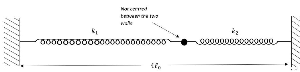
(iv) [2] Two springs, each of unstretched length $\ell_{0}$, but with different spring constants $k_{1}$ and $k_{2}$, are attached to a mass $m$ and are stretched between the two walls a distance $4 \ell_{0}$ apart, as in Fig. 18. By making a small displacement $x$ of the mass from equilibrium, obtain the equation for its period of oscillation $T$.
Figure 18: Two springs attached to a mass, which rests on a smooth horizontal plane.
b) [4] (i) Masses $m_{1}$ and $m_{2}$ resting on a smooth horizontal surface are attached to the ends of a light inextensible string of length $r$. When set in rotation they rotate about a point on the string at angular speed $\omega$. Obtain an expression for the tension $T$ in the string in terms of $m_{1}, m_{2}, r$ and $\omega$.
(ii) A light spring of constant $k$ in compression and extension, has masses $m_{1}$ and $m_{2}$ attached to the ends, as shown in Fig. 19. When disturbed the masses oscillate along the line of the spring. The system can be modelled as two springs with a nonoscillating point. Find a function of the masses $M\left(m_{1}, m_{2}\right)$, such that the period of oscillation can be expressed in the form $T=2 \pi \sqrt{\frac{M}{k}}$.
Figure 19: Two masses attached to a spring on a smooth horizontal surface.
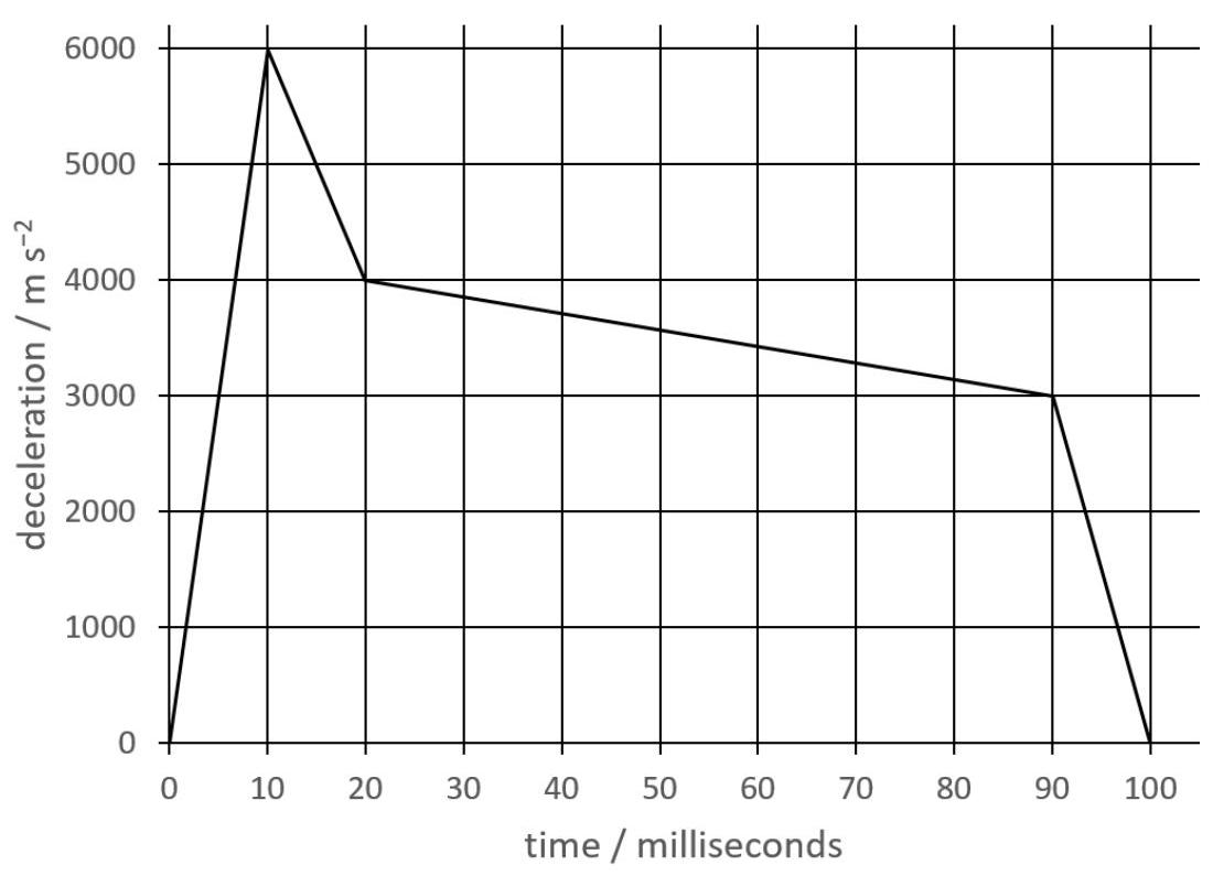
c) [5] The graph shown in Fig. 20 illustrates the deceleration of a projectile as it hits the ground.
(i) From the graph, using the average decelerations, make simple estimates of the changes in speed in each of the four deceleration regions as it comes to rest, and determine the initial speed of the projectile.
(ii) Similarly, assuming a uniform change in speed with time in each of the four regions of the graph, estimate the depth of penetration of the projectile into the ground.
Figure 20: The deceleration profile of a projectile hitting the ground at high speed.
d) [4] Approximations and making a simple model are key to doing physics. Often we require linear behaviour in our model, often associated with a small displacement from equilibrium, and also that the collision time is short compared to any other motion of the system. This we can see in the following example.
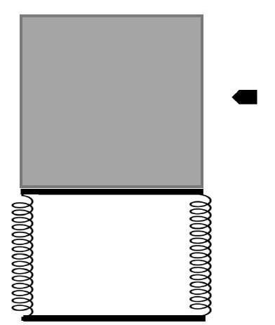
In a ballistic experiment, a bullet of mass $m_{1}=10 \mathrm{~g}$ is fired horizontally at a speed of $320 \mathrm{~m} \mathrm{~s}^{-1}$ into a rigid container of sand that is fixed to a steel framework, whose sides are represented by very strong, light springs, as shown in Fig. 21.
The steel framework together with the box has a mass of $M_{2}=4.0 \mathrm{~kg}$ and when tested, the steel frame deflects 5.0 mm when a force of 200 N is applied horizontally. What is the maximum deflection of the frame when the bullet is fired into the sand?
Figure 21: A sand box attached to a stiff steel framework represented by stiff springs, with an approaching bullet.
e) [5] The approximations mentioned above can also seen in this example.
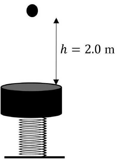
A steel ball bearing of mass $m_{1}=45 \mathrm{~g}$ is dropped from rest from a height of $h=2.0 \mathrm{~m}$. It rebounds off a steel cylinder of mass $m_{2}=0.45 \mathrm{~kg}$ which is supported by a light spring of spring constant $k=1600 \mathrm{~N} \mathrm{~m}^{-1}$, as shown in Fig. 22.
Figure 22: A steel cylinder supported by a light spring.
If the collision between the ball bearing and the cylinder is elastic,
(i) what would be the speed of the cylinder immediately after impact, and
(ii) what would be the maximum deflection of the spring? You may find it helpful to use the ratio of the masses, $r=\frac{m_{2}}{m_{1}}$.
(iii) If the collision is not elastic, then we need to have another measurement. Now the cylinder deflects by 12.0 mm from its equilibrium position as a result of the collision. Calculate the height of rebound of the ball.
2022 · Q2MechanicsMechanics: Topics on Center of Mass
This question is about Centre of Mass and Centre of Gravity.
Centre of mass has many applications in systems, and can enable otherwise complex calculations to be simplified, often in collisions and rotational dynamics.
a) [3] Two weights with masses $m_{1}$ and $m_{2}$ are attached to the ends of a light rod at distances $x_{1}$ and $x_{2}$ respectively, measured from a point that is along the line of the rod but beyond the end. A normal force, $F$, applied to some point on the rod will hold it in equilibrium.
(i) What is meant by the the word equilibrium?
(ii) By taking moments about the origin point of $x_{1}$ and $x_{2}$, show that a single force, $F$, applied normal to the rod will hold it in equilibrium, if it acts at the point given by
(iii) If an excess force $\Delta F$ is applied to the centre of mass of the rod, what is the ratio of the kinetic energy gained of $m_{1}$ to that of $m_{2}$ ?
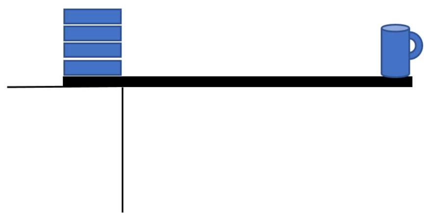
b) (i) [2] A 75 cm long uniform plank of mass 0.24 kg hangs over the edge of a table as in Fig. 1 and supports a 0.35 kg mug of tea with a diameter of 8.0 cm which sits on the end of the plank with one side on the edge. A pile of textbooks, each of mass 0.48 kg is used weigh the plank down on the table, with 15 cm of plank resting under the books that are also 15 cm wide. How many books are required to support the system?
Figure 1: Cup of tea on a plank supported by books.
(ii) [3] Two uniform, similar rods of the same material $\mathbf{A B}$ of lengths $L_{\mathrm{AB}}$ and $\mathbf{B C}$ of length $L_{\mathrm{BC}}$ respectively, are joined rigidly at B . They are suspended from A on a string and the rods hang at angles $\alpha$ and $\beta$ to the vertical.
Obtain an expression for $\frac{L_{\mathrm{AB}}}{L_{\mathrm{BC}}}$ in terms of $\alpha$ and $\beta$.
(iii) [1] A wooden stick of length $L$ and density $\rho_{\mathrm{w}}$ has a rectangular cross section of side $b$. It floats in a liquid of density $\rho_{\mathrm{l}}$. If it floats vertically, obtain an expression for the vertical difference in heights of the centres of mass of the liquid displaced and the stick, in terms of $L, \rho_{\mathrm{w}}$ and $\rho_{\mathrm{l}}$
(iv) [3] A light rod of length $L=30 \mathrm{~cm}$ has masses of 0.40 kg and 0.90 kg attached to the ends of the rod. It is thrown vertically upwards with a flick of the wrist, from a height $h$ above the ground, rotating at eight times each second, and returning to height $h$. It is given 110 J of energy initially.
How many rotations does it make before it lands?
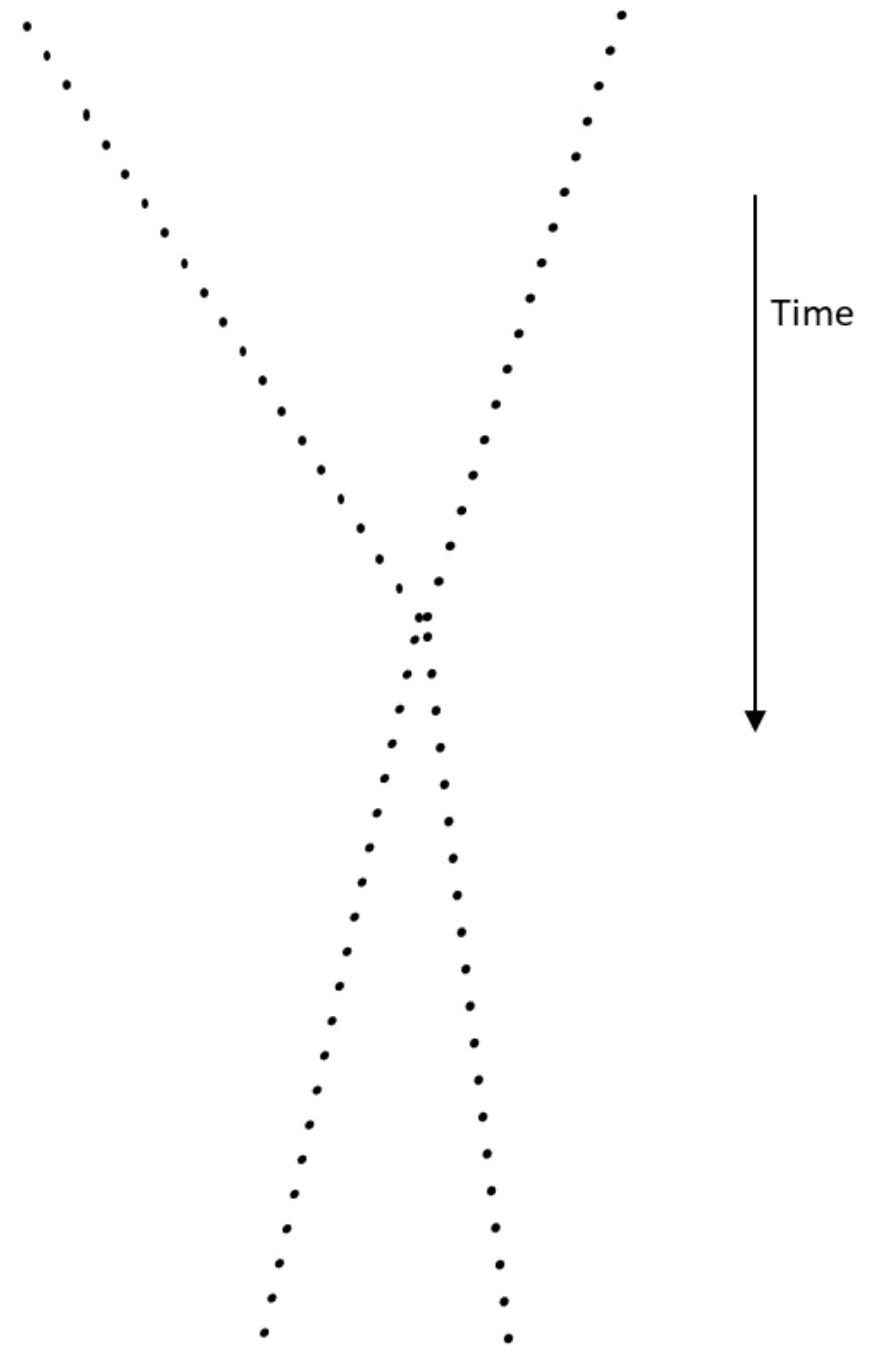
c) [2] A small ball of mass $\frac{1}{3} m$ travelling at speed $2 v$ collides linearly and inelastically with a ball of mass $\frac{2}{3} m$ moving at speed $v$. A set of equal time interval photographs are taken of the collision, and are set out in Fig. 2.
(i) Sketch this and add to it the position of the centre of mass of the particles.
(ii) From measurements of the tracks on this paper, estimate the fraction of the KE lost in the collision.
Figure 2: Collision of two particles.
d) (i) [4] A thin uniform string of mass $m$ and length $2 a$ hangs over a light, smooth pulley of negligible radius. When displaced from equilibrium, it slides off and leaves the pulley at speed $v$. Obtain an expression for $v$ in terms of $a$ and $g$.
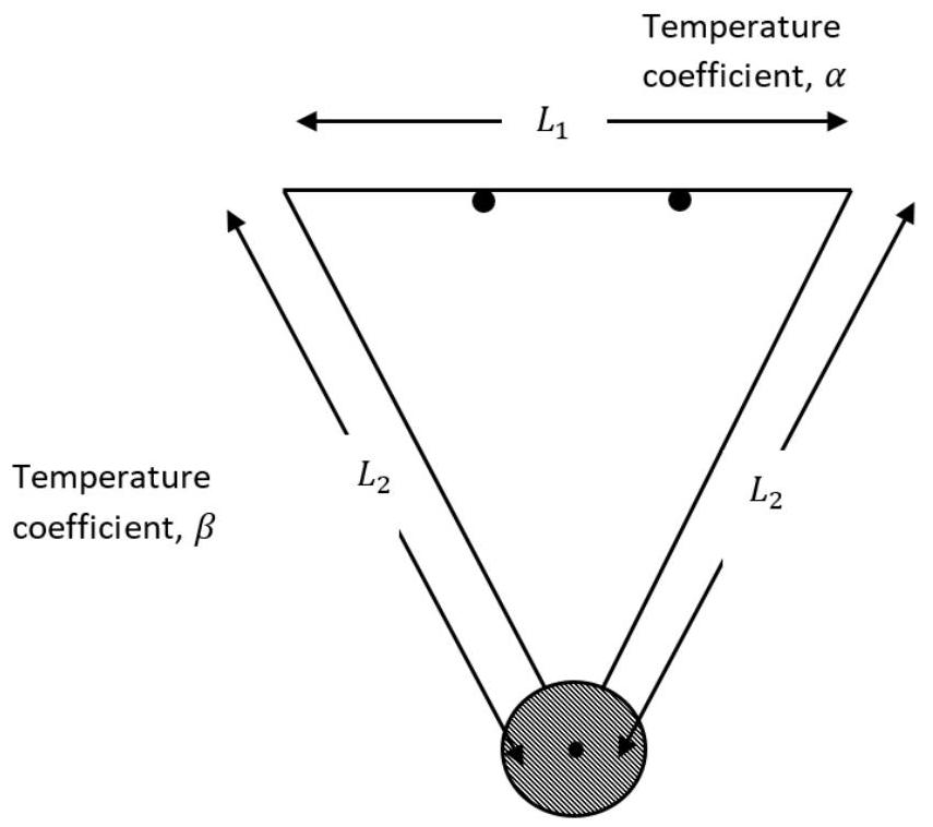
(ii) [3] In a pendulum clock, the length of the pendulum must be kept constant, independent of temperature changes, if the clock is to run at the correct rate. In the diagram of Fig. 3, a triangular support for the pendulum mass is made of an isosceles triangle of rods, the horizontal rod of length $L_{1}$ with coefficient of thermal expansion $\alpha$ in ${ }^{\circ} \mathrm{C}^{-1}$ and two sloping rods of length $L_{2}$ of a different metal with coefficient of thermal expansion $\beta$. The pendulum mass is attached at its centre and the pendulum is supported so that it can swing in and out of the page.
If the pendulum is temperature compensated for small temperature changes $\Delta T$, what is the required ratio of the lengths $\frac{L_{1}}{L_{2}}$ in terms of $\alpha$ and $\beta$ ?
Figure 3: A temperature compensated pendulum constructed from a triangular support of rods, so that it can swing in and out of the page.
(iii) [4] A light rod of length $\ell$ has two similar masses $m$ attached to the left and right ends. It is suspended horizontally by a string in a non-uniform vertical gravitational field which increases linearly in strength from $g$ at the left end to $1.1 g$ at the right end.
i. When the rod is balanced, as a fraction of $\ell$, what is the difference between the centre of mass of the system and the point of suspension (the centre of gravity)?
ii. If the string is now attached to the centre of the rod, a third mass $m$ must also be attached to the rod in order to balance it. In terms of $\ell$, how far from the left end of the rod must this mass be attached?
2023 · Q2MechanicsElectricity & MagnetismFluidsMechanics & Electricity: Wind Turbines and Power Transmission
This question is about wind turbines, high-voltage power transmission and the rectification of alternating current.
A modern off-shore wind farm is built up here in stages: first the crude “catch-all” estimate of a turbine's power, then a realistic stream-tube model that leads to the famous Betz limit, then the high-voltage cable that carries the electricity ashore, and finally the mercury-arc valve that historically converted that power between ac and dc forms.
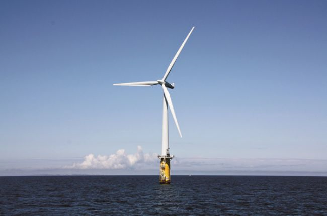
a) [3] Assuming a wind direction perpendicular to the plane of the turbine blades, determine the power if all of the kinetic energy of the wind is transferred to the blades, in terms of the density of the air $\rho$, the length of the turbine blades $r$, and the wind speed $v$.
Figure 1: A wind turbine with blades of length $r$ facing a wind of speed $v$.
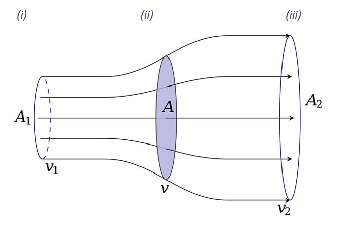
b) [9] In reality, not all of the power of the wind is extracted. The wind speed is slower behind the turbine, and the wind can be imagined to disperse over a larger area as shown in Figure 2, where $A$ shows the area swept out by the turbine. This question will attempt a more realistic model of the energy transfers in a wind turbine. Assume the density of the air remains constant.
Figure 2: The stream tube of air slowing and spreading as it passes through the turbine, with upstream region (i), turbine plane (ii) and downstream region (iii).
(i) Write down expressions for the rate of flow of air mass in region (i).
(ii) Write down expressions for the rate of flow of air mass in region (ii).
(iii) Write down expressions for the rate of flow of air mass in region (iii).
(iv) By considering the air before entry and after entry to the turbine, determine the power output of the turbine in terms of $\rho$, $A$, $v$, $v_1$ and $v_2$.
(v) If we now assume that $v$ equals the mean of $v_1$ and $v_2$, write down an expression for the power output of the turbine in terms of $\rho$, $A$, $v_1$ and $v_2$ only.
(vi) Determine the value of $v_1/v_2$ which gives a maximum in the output of the turbine.
(vii) Determine the maximum power output of the turbine in terms of $\rho$, $A$ and the prevailing wind speed $v_1$.
(viii) The newest off-shore wind turbines in the North Sea have a blade length of $107\,\mathrm{m}$, and the average wind speed is $10\,\mathrm{m\,s^{-1}}$. Calculate the maximum possible power output from this turbine.
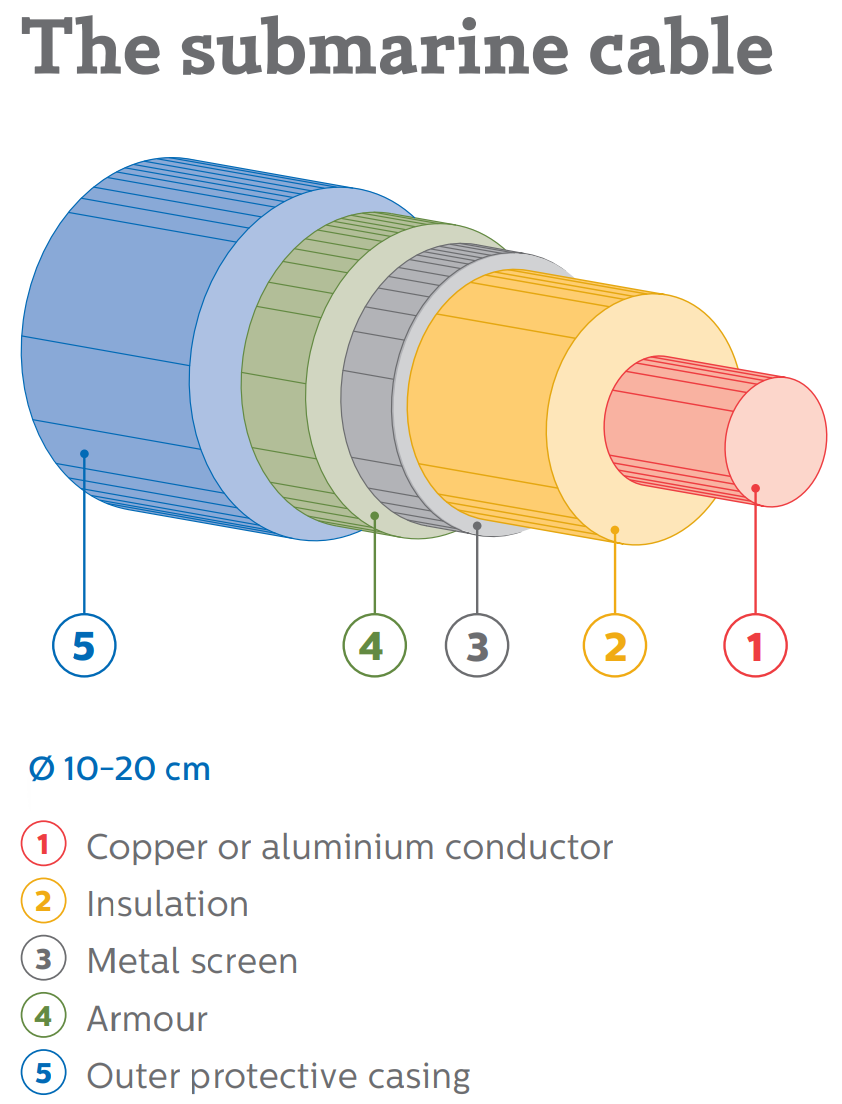
c) [7] The electrical power from the wind farm is transferred to the shore using High Voltage Direct Current (HVDC) at $320\,\mathrm{kV}$ with respect to earth. The cable used to transfer the power will typically consist of a $2.2\,\mathrm{cm}$ radius copper core, surrounded by cross-linked polyethylene (XLPE) insulation of radius $4.0\,\mathrm{cm}$ which itself is surrounded by a protective metal screen. The greatest length in a North Sea project will be $265\,\mathrm{km}$. The resistivity of copper is $1.68 \times 10^{-8}\,\Omega\,\mathrm{m}$ and of XLPE is $1.97 \times 10^{14}\,\Omega\,\mathrm{m}$.
Figure 3: Cross-section of the HVDC cable: copper core, XLPE insulating shell, and metal screen.
(i) Calculate the resistance of the copper core and the power dissipated as heat, and percentage loss in the copper, if the cable transfers $800\,\mathrm{MW}$ of power.
(ii) Calculate the resistance of the XLPE insulation between the copper core and the metal screen, and hence calculate the leakage current, power and percentage loss due to the leakage current, when operating at $320\,\mathrm{kV}$.
(iii) The thermal conductivity of XLPE is $0.28\,\mathrm{W\,m^{-1}\,K^{-1}}$. Assuming the temperature drop across all thermal barriers except the XLPE is negligible, calculate the operating temperature of the copper core at $800\,\mathrm{MW}$ given the ambient sea temperature is $7.0\,^\circ\mathrm{C}$.
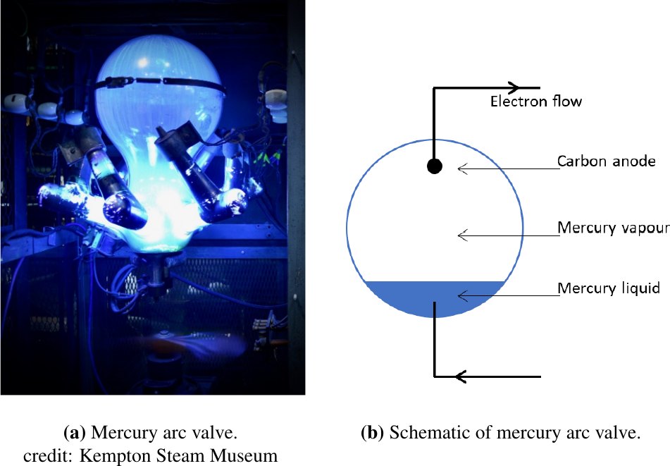
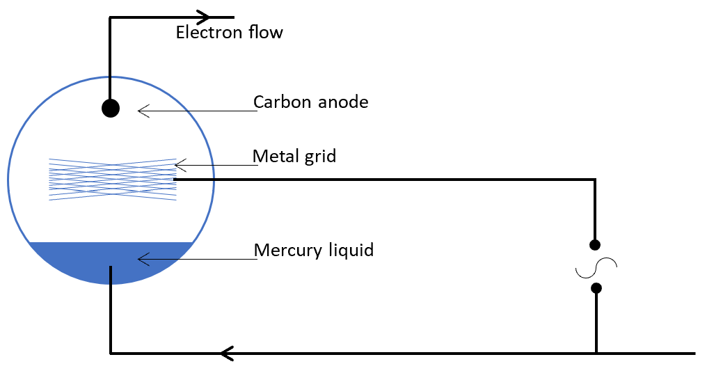
d) [6] High current rectification (ac to dc conversion), and inversion (dc to ac conversion) was until relatively recently achieved using a device called a mercury arc valve (see Figure 4a). In its simplest schematic form in Figure 4b the principle of operation is that the mercury vapour at low pressure ($7.0\,\mathrm{mPa}$ and $40\,^\circ\mathrm{C}$) becomes ionised and the ions collide with the mercury liquid which liberates electrons. These then become available to carry the current to the carbon anode, and also via collision with atoms of mercury vapour produce mercury ions to replace those reabsorbed into the liquid phase. There is no appreciable electron emission from the carbon anode and so the current flows in one direction only in the manner of a diode.
Figure 4: A mercury arc valve and its schematic form acting as a one-way “diode”.
(i) Estimate the forward bias potential of this “diode”.
(ii) Inserting a grid between the anode and the mercury cathode allows the electron current to be modulated and thus an ac current produced from a dc supply. The anode current is given by $I = a + bV_g + cV_g^2$, and $V_g = A + B\cos(\omega t)$, that is a constant bias and an oscillatory signal. The anode current contains a second harmonic component. Determine its amplitude.
Figure 5: The grid-controlled anode current, showing the modulated waveform.
(iii) The mean value of the anode current contains a term proportional to $B^2$. Obtain the coefficient of this term.
(iv) If $I_0$ is the value of $I$ when $B = 0$ and, when the signal is applied, $I$ oscillates between $I_{\max}$ and $I_{\min}$, express the ratio of the amplitudes of the second harmonic and fundamental (1st harmonic) in terms of the quantity $\chi$, which is defined as
$$\chi = \frac{I_{\max} - I_0}{I_0 - I_{\min}}.$$
(Hint: a useful identity is $\cos^2\theta - \sin^2\theta = \cos 2\theta$.)
[25 marks]
Show answer · 显示答案
Answers
(a)$\displaystyle P = \tfrac{1}{2}\rho\,\pi r^2 v^3$
2024 · Q3MechanicsFluidsMechanics: Bubbles, Forces and Rotation
This question is about bubbles, forces and rotation.
A slowly sinking soap bubble is treated as a body in steady (terminal) motion, where buoyancy, drag and weight balance. As the soap film evaporates the bubble lightens until it rises, and the same force balance is used to extract the buoyancy, the lost mass and the film thickness. The ideas of rotation and circumferential tension are then developed, first for discrete masses on strings, then for a continuous hoop using dimensional analysis, and finally for the radial oscillation of an elastic ring.
a) [10] A spherical soap bubble is filled with warm air but, due to the weight of the liquid film, the bubble sinks slowly at speed $v$ in the surrounding cooler air. As the soap film evaporates, the bubble becomes lighter and eventually starts to rise. We wish to determine the length of time it takes between it falling at speed $v$ in still air and then, a short time later, the bubble rising in still air at speed $v$.
Figure 4: A soap bubble of radius $r$ filled with warm air, sinking in cooler room air.
The heavier (sinking) and lighter (rising) masses of the bubble are $m_{\mathrm{h}}$ and $m_{\ell}$ respectively. The bubble has a radius $r = 8.0\,\mathrm{cm}$, the density of the soap solution is $998\,\mathrm{kg\,m^{-3}}$, and the soap film evaporates from the outer surface at a rate of $2.4 \times 10^{-5}\,\mathrm{kg\,m^{-2}\,s^{-1}}$.
(i) Using the fact that the magnitude of the drag force, $F_{\mathrm{d}}$, is the same when the bubble is falling as when it is rising, obtain two equations, for the buoyancy, $B$, and for $F_{\mathrm{d}}$, acting on the bubble in terms of $m_{\mathrm{h}}$, $m_{\ell}$ and $g$.
(ii) Calculate the magnitude of the buoyancy force, when the air inside is at $25\,^{\circ}\mathrm{C}$ and the cooler air in the room is at $17\,^{\circ}\mathrm{C}$. Take atmospheric pressure as $1.01 \times 10^{5}\,\mathrm{Pa}$ and the molar mass of the air inside and outside to be $28\,\mathrm{g\,mol^{-1}}$. Ignore the extra pressure due to the soap film, and the water vapour inside the bubble.
(iii) The slow speed of motion means that $F_{\mathrm{d}} = kv$ with $k = 1.2 \times 10^{-3}\,\mathrm{N\,s\,m^{-1}}$. Calculate how long it would take for sufficient mass of the soap film to have evaporated from the outside surface of the bubble so that the velocity changes from $6.0\,\mathrm{cm\,s^{-1}}$ downwards to $6.0\,\mathrm{cm\,s^{-1}}$ upwards.
(iv) Calculate the initial thickness of the bubble wall.
b) [10]
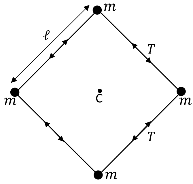
(i) Four identical masses, $m$, are attached to each other by four light strings of equal length $\ell$, as in Fig. 5.
Figure 5: Four equal masses joined by four light strings, rotating about the centre C.
The system rotates in the plane of the masses about the centre C, with each mass moving at speed $v$ in a circle. Obtain expressions for the radial $T_{\mathrm{r}}$ and tangential $T_{\mathrm{tangential}}$ components of the tension $T$ in the string, in terms of $m$, $v$ and $\ell$.
When the masses are not discrete but continuous, a modified approach is used.
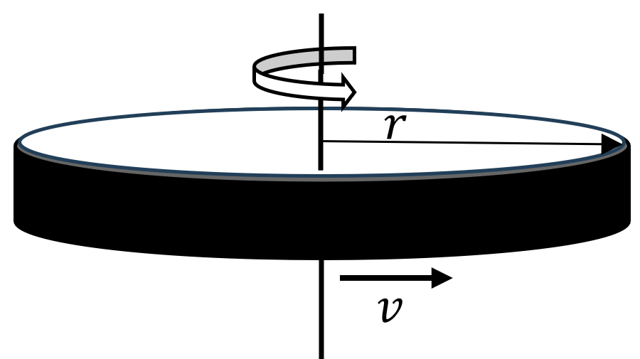
(ii) A thin circular hoop of mass $m$ and radius $r$ is rotated in a horizontal plane about its centre with speed $v$ as in Fig. 6. The hoop has a mass per unit length (linear density) of $\lambda$.
Figure 6: A thin circular hoop rotated about its centre in a horizontal plane.
The tension $T_{\mathrm{tangential}}$ in the hoop holding it together is given by the expression
$$T_{\mathrm{tangential}} = k\,\lambda^{\alpha} v^{\beta} r^{\gamma}$$
where $k$ is a dimensionless quantity. By considering the dimensions (or units) of the terms in this expression, and assuming $k = 1$, obtain an equation for $T_{\mathrm{tangential}}$.
(iii) A rubber band of mass $25\,\mathrm{g}$ which behaves linearly, has an unstretched length of $15.0\,\mathrm{cm}$ and a spring constant of $2000\,\mathrm{N\,m^{-1}}$. It is stretched round a horizontal flywheel (a disc) of circumference $18.5\,\mathrm{cm}$. At what speed of rotation of the disc will the band fall off?
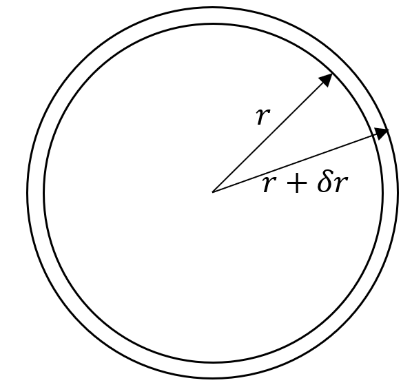
c) [5] A thin, elastic ring of mass $m$ and radius $r$ of Fig. 7 oscillates at its lowest natural frequency in a radial direction, expanding and contracting. The circumferential tension in the ring is proportional to the extension of the circumference i.e. $T = k\,\delta x$ where $\delta x$ is the extension of the ring circumference and $k$ is a constant. Determine an expression for frequency, $f$, of radial oscillations in terms of $\lambda$ (the mass per unit length), $r$ and $k$.
Figure 7: A thin elastic ring oscillating radially, expanding and contracting.
2024 · Q4MechanicsThermal PhysicsModern & Nuclear PhysicsFluidsMechanics & Thermal Physics: Landing a Craft on Titan
This question is about the physics of landing a craft on Titan.
NASA's Dragonfly mission will deliver a rotorcraft lander to Saturn's largest moon, Titan. Power comes from the radioactive decay of plutonium, heat must be retained against the bitterly cold surroundings, and the craft must hover and cruise through Titan's dense atmosphere under its weak gravity. The question works through each of these stages in turn, from the nuclear power source, through thermal insulation and rotor aerodynamics, to the physics of atmospheric entry.
a) [3] A Radioisotope Thermoelectric Generator (RTG) uses the heat produced during radioactive decay as a source of energy, (as in NASA's Dragonfly expedition to Saturn's large moon Titan).
The core of a typical unit consists of $4.8\,\mathrm{kg}$ of plutonium-238 dioxide. The energy is produced by the $5.5\,\mathrm{MeV}$ alpha decay of Pu-238, with a half-life of $87.7\,\mathrm{years}$. Calculate the initial thermal power output.
b) [2] The ambient temperature on Titan is $-179\,^\circ\mathrm{C}$. The inside of the landing craft is maintained at $0\,^\circ\mathrm{C}$, insulated with $5.0\,\mathrm{cm}$ thick Rohacell foam that has a thermal conductivity of $0.035\,\mathrm{W\,m^{-1}\,K^{-1}}$. If the internal heat source is producing $2000\,\mathrm{W}$ of power, estimate the internal area of the lander.
Hint: the rate of heat flow through a conductor, $\dfrac{\mathrm{d}Q}{\mathrm{d}t}$, is proportional to the cross sectional area it flows through, $A_c$, the temperature difference, $\Delta T$, and inversely proportional to the thickness of conductor, $\Delta x$. The constant of proportionality is the thermal conductivity.
c) [10] The landing craft is equipped with eight rotors for the purpose of flying as a drone.
(i) The force acting on the air by all eight rotor blades, $F_8$, is used to lift and drive the craft. Give an expression for the hovering lift force, $F_{\text{lift}}$, in terms of the speed of the air downwards, $v$, the density of the atmosphere on Titan, $\rho_{\text{T}}$, and the area swept out by the eight rotors, $A_8$.
(ii) Hence obtain an expression for the power, $P$, needed to hover, in terms of the mass of the craft $m_{\text{D}}$, the gravitational field strength on Titan $g_{\text{T}}$, $A$ and $\rho_{\text{T}}$.
(iii) Using the data below, calculate the ratio of the power needed to hover on Titan to the power needed to hover on Earth, $P_{\text{T}}/P_{\text{E}}$.
(iv) Calculate the hover power required by the craft on Titan.
$\rho_{\text{T}}$
$5.35\,\mathrm{kg\,m^{-3}}$
$\rho_{\text{E}}$
$1.22\,\mathrm{kg\,m^{-3}}$
$g_{\text{T}}$
$1.35\,\mathrm{N\,kg^{-1}}$
$g_{\text{E}}$
$9.81\,\mathrm{N\,kg^{-1}}$
$m_{\text{D}}$
$420\,\mathrm{kg}$
length of each rotor blade
$0.68\,\mathrm{m}$
(v) The efficiency of the conversion of heat to electrical energy is too low to allow the RTG to power flight. Estimate how long the onboard battery would need to be charged using the RTG at an efficiency of $6\%$, in order to complete a flight of $8\,\mathrm{km}$ at an altitude of $500\,\mathrm{m}$ at $10\,\mathrm{m\,s^{-1}}$, including ascending and descending. Assume the density of the atmosphere does not change over this altitude, there are no losses due to drag, the craft can also rise and fall vertically at a constant $10\,\mathrm{m\,s^{-1}}$. In ascending it consumes power at its hovering rate plus the GPE gained, whilst in descending it consumes power only at its hovering rate.
d) [6] The rotor driving force, $F_8$, is a function of $\rho_{\text{T}}$, $A_8$, and the rotation speed of the tips of the rotors, $v_{\text{tip}}$, and is given by $F_{\text{drive}} = C_{\text{L}}\rho_{\text{T}}A_8 v_{\text{tip}}^2$, where $C_{\text{L}} \approx 1$.
The drag force, $D$, on the landing craft can be approximated in a similar way, with $D = C_{\text{D}}\rho_{\text{T}}A_8 v_{\text{air}}^2$, where $v_{\text{air}}$ the airspeed of the craft and $C_{\text{D}} \approx 1$.
(i) When the craft is at constant speed in horizontal flight the driving force, $F_8$, of the rotors is required to counter the drag force by providing thrust $T$, and countering the weight, $W$, of the craft by providing lift, $L$. Show all five of these listed forces, $T, D, W, L, F_8$, on a diagram and write down an expression for the magnitude of $F_8$ in terms of $D$ and $W$.
(ii) Substituting the expressions for each of these forces, obtain an expression for the airspeed, $v_{\text{air}}$, in terms of $\rho_{\text{T}}$, $A$, $m_{\text{D}}$, $g_{\text{T}}$ and $v_{\text{tip}}$.
(iii) From your expression calculate the velocity for horizontal flight given a rotor speed of $500\,\mathrm{rpm}$.
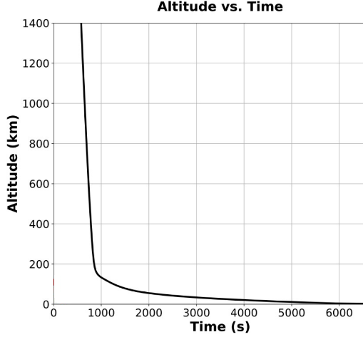
e) [4] The space capsule containing the Dragonfly landing craft enters the atmosphere of Titan and for much of its travel through the outer atmosphere of the moon the velocity is approximately constant at $7300\,\mathrm{m\,s^{-1}}$, as seen in the graph of Fig. 8. The resistance to motion provided by the tenuous atmosphere is determined by the turbulent flow of the atmosphere around the capsule.
Figure 8: Graph of Dragonfly entering the Titan atmosphere and landing.
(i) The resistive force acting on the approximately spherical capsule, assuming turbulent flow, will be given by $F = k\rho^{\alpha}v^{\beta}r^{\gamma}$, where $k$ is a dimensionless constant, $\rho$ is the density of the atmosphere of Titan, $v$ is the speed of the capsule, and $r$ is the radius of the capsule. Using dimensions or otherwise, determine the coefficients $\alpha, \beta, \gamma$ and write the equation for $F$.
(ii) Taking $k = 1$ and the diameter of the capsule to be $3.7\,\mathrm{m}$, estimate the density of the atmosphere at an altitude of $600\,\mathrm{km}$.
Mass of Titan
$= 1.345 \times 10^{23}\,\mathrm{kg}$
Mass of capsule
$= 400\,\mathrm{kg}$
Radius of Titan
$= 2575\,\mathrm{km}$
[25 marks]
Show answer · 显示答案
Answers
(a)$\displaystyle P \approx 2680\,\mathrm{W} \approx 2.7\,\mathrm{kW}$
Motor racing brings together several strands of mechanics in a single setting. Here we work through the relative velocity of two cars on a circuit, the way engine power and aerodynamic drag together set how quickly a car accelerates, the friction that lets a wheel grip a wall, and finally the way a hot engine cools once the race is over.
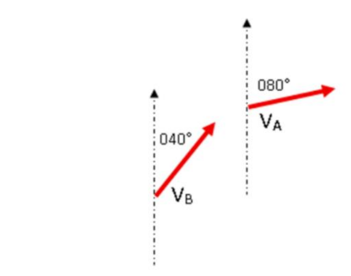
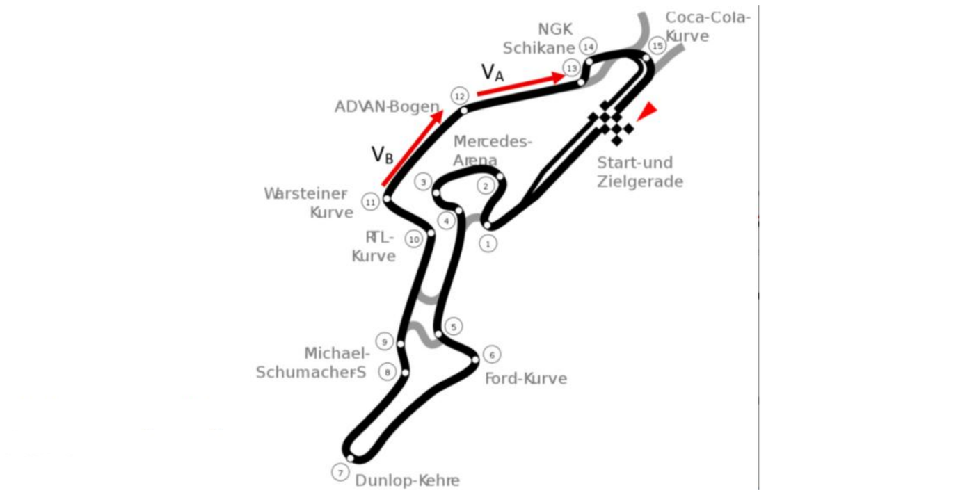
a) [4] Determine the relative velocity and the bearing of car A relative to car B when $v_A = 220\,\mathrm{km\,h^{-1}}$ and $v_B = 250\,\mathrm{km\,h^{-1}}$. You must include a clear diagram.
Figure 1: Cars A and B with their corresponding velocities shown.
Figure 2: Cars A and B on the track.
b) [10] A car of mass $M$ is driven by an engine transferring power $P$. Resistive forces opposing the motion of the car are directly proportional to the square of the car's speed. The maximum achievable speed of the car is $v_{\max}$. During the race, the car increases its speed from $u$ to $v$ over a distance $x$.
(i) Derive an expression for the rate of change of speed with distance in terms of the mass $M$, power $P$, maximum speed $v_{\max}$, $v$, and $u$.
(ii) Find the distance $x$ in terms of $M$, $v_{\max}$, $v$, $u$, and $P$.
(iii) If the maximum speed of the car is $v_B = 375\,\mathrm{km\,h^{-1}}$, the engine transfers $750\,\mathrm{kW}$ of power and the mass of the car and driver is $800\,\mathrm{kg}$, determine the distance covered in increasing the speed from $100\,\mathrm{km\,h^{-1}}$ to $200\,\mathrm{km\,h^{-1}}$.
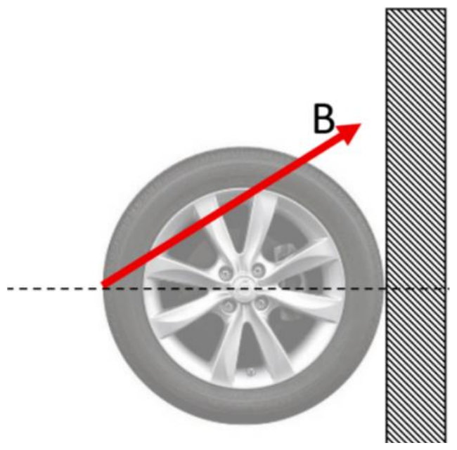
c) [5] A wheel of weight $W$ is attached to a wall by a belt B attached to the horizontal diameter of the tyre as shown in Fig. 3. If the coefficient of friction with the wall is $\mu = 1.6$ for the rubber tyre, determine the maximum possible angle above the horizontal (between the belt and the horizontal diameter) that may be used before the wheel slips to the ground.
Figure 3: Wheel hanging from a wall.
d) [6] An F1 car engine has an operating temperature of $110\,^\circ\mathrm{C}$. According to Newton's law of cooling the rate of decrease of temperature of a body is directly proportional to the difference in temperature between the body and its surroundings. With an ambient temperature of $20\,^\circ\mathrm{C}$, once stopped, if the engine takes $30$ minutes to cool to $50\,^\circ\mathrm{C}$, how long would it take to cool to $80\,^\circ\mathrm{C}$ after stopping?
(a)$v_{AB}\approx163.2\,\mathrm{km\,h^{-1}}$, bearing $159.95^\circ$. Corrected — the printed 80° is a triangle angle, not the bearing; see the interactive walkthrough.