BPhO R1 S2 · Section 2

Electricity & Magnetism

10 questions — reveal each final answer.

2017 · Q2Electricity & MagnetismCircuit and Resistor

a) [6] A $50 \mathrm{~Hz}$ alternating current of $10 \mathrm{~A}$ (rms) passes along a copper wire whose diameter is $1.0 \mathrm{~mm}$. If copper contains $9.0 \times 10^{22}$ free electrons per $\mathrm{cm}^{3}$, estimate

(i) the maximum speed of the electrons, and

(ii) the maximum displacement of the electrons associated with the current.

b) [6] A wire of length $l$ and resistance $R$ is extended by an amount $\varepsilon$ such that $\varepsilon \ll l$. If the volume of the wire and its resistivity remain unchanged,

(i) Give an expression for the fractional change in $R$, i.e. $\frac{\delta R}{R}$.

(ii) Calculate the new resistance of the wire if $R=100.0 \Omega$ and $\varepsilon / l=0.001$.

c) [6] A non-linear electrical component is connected in a circuit in series with a supply of emf $\varepsilon=300 \mathrm{~V}$ and negligible internal resistance, and a resistor $R$ of $4.0 \mathrm{k} \Omega$. The relation between the current $I$ through the non-linear component, and the potential difference across it, $V_{c}$, is given by $I=A V_{\mathrm{c}}+B V_{\mathrm{c}}^{2}$ where $A=0.070 \mathrm{~mA} \mathrm{~V}{ }^{-1}, B=0.0050 \mathrm{~mA} \mathrm{} \mathrm{V}^{-2}$.

(i) Obtain an algebraic expression for $V_{c}$.

(ii) Determine the current $I$ through the non-linear component.

d) [7] A metal hemisphere of radius $0.10 \mathrm{~m}$ is immersed near the centre of a large conducting tank containing a liquid of resistivity $60 \Omega \mathrm{m}$. The plane surface of the hemisphere is level with the surface of the liquid.

(i) Find an expression for the resistance between two hemispherical shells within the liquid, concentric with the centre of the metal hemisphere, having radii $r$ and $(r+\delta r)$ respectively.

(ii) Calculate the resistance between the hemisphere and the tank.

Show answer · 显示答案
Answers
  • (a)(i)$\displaystyle v_{\text{max}} = 1.25 \times 10^{-3} \, \text{m/s}$
  • (a)(ii)$\displaystyle 3.98 \times 10^{-6} \, \text{m}$
  • (b)(i)$\displaystyle 2 \frac{\varepsilon}{l}$
  • (b)(ii)$\displaystyle 100.2 \, \Omega$
  • (c)(i)$\displaystyle 94.6 \, \text{V}$
  • (c)(ii)$\displaystyle 0.0513 \, \text{A}$
  • (d)(i)$\displaystyle dR = \frac{\rho \delta r}{2 \pi r^2}$
  • (d)(ii)$\displaystyle 95.5 \, \Omega$

Worked solutions are in the book.
2017 · Q5Electricity & MagnetismMechanicsCharge, Electric Field and Potential

a) [6] A simple pendulum of string length $l$, with a bob of mass $m$, containing charge $Q$, is in a horizontal electric field of magnitude $E$.

(i) Determine the angle of the string with respect to the vertical when the bob is in equilibrium.

(ii) If the electric field now points vertically downwards and there is a small negative charge on the bob, $-Q$, such that the string remains taut, what would be the period of oscillation of the bob once perturbed?

(iii) Give the condition relating $Q, E, m$ and $g$, such that oscillations will occur when the bob is perturbed.

b) [10] Equal and opposite charges $+Q$ and $-Q$ are a distance of $2 a$ apart. Taking the midpoint between them as the origin $\mathrm{O}$, find the electric potential and the magnitude of the field strength, at a point $\mathrm{P}$ which is distance $r(r \gg a)$ from $\mathrm{O}$, when

(i) $\mathrm{P}$ is on the line passing through the charges;

(ii) When $\mathrm{P}$ is on a perpendicular bisector of the line joining the charges.

c) [2] Equal and opposite charges separated by a small distance constitute a dipole. A hydrogen chloride molecule may be treated as a dipole in which an electron is separated from a positive charge of equal magnitude by a distance of $2 \times 10^{-11} \mathrm{~m}$. Calculate the work done needed to turn the molecule, which is lying parallel to a field of $3 \times 10^{5} \mathrm{~V} \mathrm{~m}^{-1}$, through an angle of $180^{\circ}$.

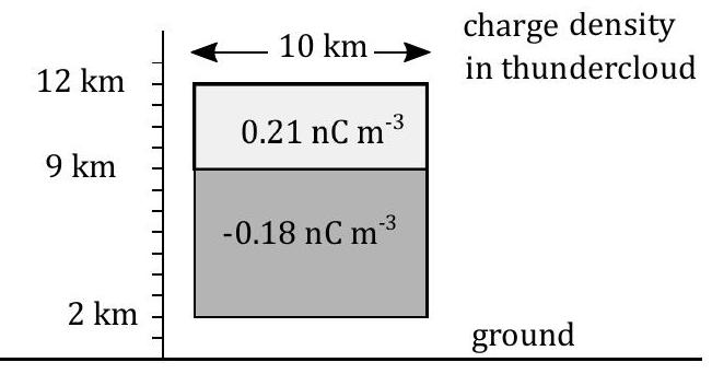
d) [7] In a simple model of a thundercloud, an upper cylindrical shaped region (axis vertical) contains a net positve charge and the lower cylindrical shaped region of the cloud a net negative charge, as shown in Figure 6. The upper region, from $9 \mathrm{~km}$ to $12 \mathrm{~km}$ height, with a radius of $5 \mathrm{~km}$ has a charge density of $0.21 \mathrm{nC} \mathrm{m}^{-3}$, whilst the lower region from $2 \mathrm{~km}$ to $9 \mathrm{~km}$ high, also with a radius of $5 \mathrm{~km}$, has a charge density of $-0.18 \mathrm{nC} \mathrm{m}^{-3}$.

figure

Figure 6: ref. Mazur V, LH Runhke: JGR, v103, D18, pp23299-23308, 1998

(i) Calculate the magnitudes of the positive and negative charges in each region.

In order to determine the field strength at the ground due to these charges, we can aproximate these two volumes of charge as two point charges at the centres of each of the two regions (at heights $10.5 \mathrm{~km}$ and $5.5 \mathrm{~km}$ respectively). The ground is a good conducting plane surface and so charges will be induced in the surface. The effect of this induced charge can be simulated by considering a charge of equal magnitude but opposite sign at the same distance $h$ below the surface as the real charge at height $h$ above the surface. The field at the surface is then calculated from the field of the real charge at the surface added to the field due to the image charge at the surface.

(ii) For the two charges calculated, with their two image charges of opposite signs, calculate the strength of the electric field at the surface of the Earth directly below the thundercloud.

(iii) If a two metre tall person stands with his feet on the ground in this region, what is the magnitude and polarity of the potential at his head? Take the potential of the ground to be $0 \mathrm{~V}$.

Show answer · 显示答案
Answers
  • (a)(i)$\displaystyle \theta = \tan^{-1} \left(\frac{QE}{mg}\right)$
  • (a)(ii)$\displaystyle T = 2 \pi \sqrt{\frac{l}{g - \frac{QE}{m}}}$
  • (a)(iii)$\displaystyle QE < mg$
  • (b)(i)$\displaystyle V_P = \frac{2 Q a}{4 \pi \varepsilon_0 r^2}$$\displaystyle E_P = \frac{ Q a}{ \pi \varepsilon_0 r^3}$
  • (b)(ii)$\displaystyle V_P = 0$$\displaystyle \frac{2 Q a}{4 \pi \varepsilon_0 r^3}$
  • (c)$\displaystyle 1.92 \times 10^{-24} \, \text{J}$
  • (d)(i)$\displaystyle 49.47 \, \mathrm{C}$$\displaystyle -98.99 \, \mathrm{C}$
  • (d)(ii)$\displaystyle -50.8 \, \mathrm{kV/m}$
  • (d)(iii)$\displaystyle -101.6 \, \mathrm{kV}$

Worked solutions are in the book.
2018 · Q5Electricity & MagnetismCircuit

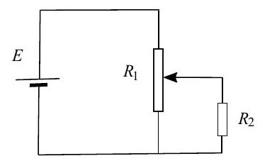
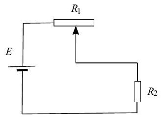
a) [5] In the two circuits shown in Figures $6 \mathbf{a}$ and $6 \mathbf{b}$ below, a cell of e.m.f. $E$ and negligible internal resistance is connected across a pair of resistors, $R_{1}$ and $R_{2}$. Resistor $R_{1}$ is a length of uniform resistance wire, and $R_{2}$ is a fixed resistor.

(i) For the circuit shown in Figure $6 \mathbf{a}$, sketch two graphs on the same axes showing how the potential $V$ across $R_{2}$ varies with position of the sliding contact on $R_{1}$ for the cases

i. when $R_{2} \gg R_{1}$

ii. when $R_{2} \ll R_{1}$

(ii) Repeat part (i) above for the circuit shown in Figure 6b.

(iii) What are the relative advantages of each of these circuits when used to control the potential difference across $R_{2}$ ?

figure

Figure 6 (a)

figure

Figure 6 (b)

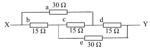
b) [4] A resistance network is shown in Figure 7 .

figure

Figure 7

(i) A total current of $10 \mathrm{~mA}$ flows through the circuit. Determine the current in each of the resistors, a to e.

(ii) Hence find the total resistance between $X$ and $Y$.

c) [6] A strain gauge consists of a straight metal wire of length $0.30 \mathrm{~m}$, diameter $0.028 \mathrm{~mm}$ and resistivity $5.0 \times 10^{-7} \Omega \mathrm{m}$. Calculate the resistance of the gauge when

(i) unstrained and

(ii) stretched by $1.0 \mathrm{~mm}$. You may assume that the diameter of the wire does not change.

(iii) Calculate the resistance if the stretched wire maintained the same volume i.e. the diameter decreased in the process of stretching?

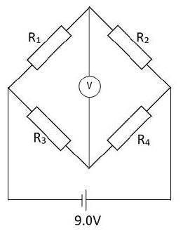
(iv) Four identical strain gauges as in c) (ii) above, labelled $R_{1}$ to $R_{4}$, are arranged in a bridge circuit as shown in Figure 8 , with a cell of e.m.f $9.0 \mathrm{~V}$ and of negligible internal resistance. $R_{1}$ and $R_{4}$ are stretched by $1.0 \mathrm{~mm}$. Assuming the internal resistance of the power supply is negligible, calculate the reading on the voltmeter (which can be considered to have an infinite resistance).

figure

Figure 8

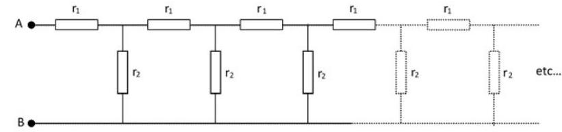
d) [4] The following network shown in Figure 9 is infinite. Find an expression for the resistance between $\mathrm{A}$ and $\mathrm{B}$ in as simple a form as possible, and determine the resistance when $r_{1}=4 \Omega$ and $r_{2}=$ $15 \Omega$. Hint: consider adding new resistors $r_{1}$ and $r_{2}$ at the left end of the circuit shown.

figure

Figure 9

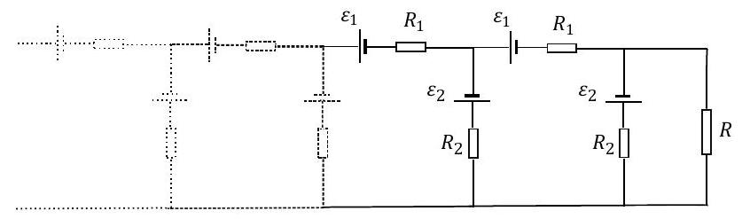
e) [6] The network shown in Figure $\mathbf{1 0}$ consists of an infinite number of cells of e.m.f. $\varepsilon_{1}$ and $\varepsilon_{2}$ with corresponding internal resistances $R_{1}$ and $R_{2}$ respectively. A resistor $R$ of value $R=1.0 \Omega$, is connected to the end of the series. If the values of the e.m.f.s and resistances are $\varepsilon_{1}=1.0 \mathrm{~V}$, $\varepsilon_{2}=2.0 \mathrm{~V}, R_{1}=4 \Omega, R_{2}=6 \Omega$, determine the value of the current flowing through resistor $R$.

figure

Figure 10

Show answer · 显示答案
Answers
  • (b)(i)$\displaystyle I_a = I_e = 4 \, \mathrm{mA}$$\displaystyle I_b = I_d = 6 \, \mathrm{mA}$$\displaystyle I_c = -2 \, \mathrm{mA}$
  • (b)(ii)$\displaystyle 21 \, \Omega$
  • (c)(i)$\displaystyle 244 \, \Omega$
  • (c)(ii)$\displaystyle 244.8 \, \Omega$
  • (c)(iii)$\displaystyle 245.2 \, \Omega$
  • (c)(iv)$\displaystyle 0.015 \, \mathrm{V}$
  • (d)$\displaystyle 10 \, \Omega$
  • (e)$\displaystyle 0.5 \, \mathrm{A}$

Worked solutions are in the book.
2018 · Q6Electricity & MagnetismCapacitor

a) [6] Two uncharged capacitors with values $C_{1}$ and $C_{2}$, are connected in series with a battery of e.m.f. $V$, and a switch. When the switch is closed there is a charge of $Q_{1}$ and $Q_{2}$ on the capacitors respectively.

(i) State the relationship between $Q_{1}$ and $Q_{2}$.

(ii) State expressions for the potential differences across each capacitor, $V_{1}$ and $V_{2}$

(iii) Hence derive an expression for the equivalent capacitance, $C_{\text {eq }}$ produced by $C_{1}$ and $C_{2}$ in series.

(iv) Write down expressions for the total energy stored in the two capacitors, and the energy supplied by the battery, in terms of $C_{\text {eq and }} V$, and comment on the difference.

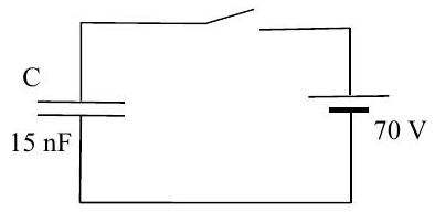
b) [2] A $15 \mathrm{nF}$ parallel plate capacitor is connected across a $70 \mathrm{~V}$ battery, as in Figure 11. How much work must be done in order to double the plate separation

(i) with the battery disconnected,

(ii) with the battery connected?

figure

Figure 11

c) [9] (i) Two capacitors, of capacitance $2.0 \mu \mathrm{F}$ and $4.0 \mu \mathrm{F}$, are each given a charge of $120 \mu \mathrm{C}$. The positive sides are then connected, as are the negative sides. Calculate:

i. The new potential difference across the plates.

ii. The change in the energy stored.

(ii) A conducting metal sphere is insulated from the ground. It is initially charged by contact with a small metal disc which carries a charge $q$, so that the sphere gains charge $Q$. The metal disc is then again given a charge $q$, and is then touched on the sphere a second time. If this process is repeated indefinitely, what would be the final charge on the sphere, $Q_{f}$ ?

(iii) Three capacitors with leads $A B, C D$ and $E F$ of capacitances $1 \mu \mathrm{F}, 2 \mu \mathrm{F}$ and $3 \mu \mathrm{F}$ respectively are each connected separately to a battery and charged to a potential of $12 \mathrm{~V}$. The positively charged plates are $A, C$ and $E$. The capacitors are joined in series so that $B$ is connected to $C, D$ is connected to $E$, and $F$ is connected to $A$.

i. Calculate the charges on each of the capacitors, indicating the values and signs on a diagram.

ii. Sketch a graph to show the variation of potential around the circuit from $A$ to $F$.

d) [4] A pair of concentric conducting spheres have radii of $10 \mathrm{~cm}$ and $15 \mathrm{~cm}$ respectively. They are insulated from each other, and the potential difference between the spheres is $120 \mathrm{~V}$. The spheres carry equal charges $\pm Q$, with the inner sphere being positive..

(i) Sketch the shape of a graph of the electric field strength between $r=0 \mathrm{~cm}$ and $r=30 \mathrm{~cm}$.

(ii) Sketch a graph of the potential between $r=0 \mathrm{~cm}$ and $r=30 \mathrm{~cm}$.

(iii) Write down expressions for the potential on the inner charged sphere if the outer sphere were not present, and the potential for the outer charged sphere if the inner sphere were not present.

(iv) From these results, calculate the magnitude of the charge $Q$

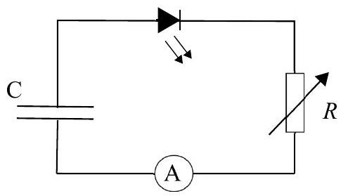
e) [4] An LED is to be lit with a constant current of $800 \mathrm{~mA}$ supplied by a charged capacitor, $C$, in series with a variabl resistor, $R$, as shown in Figure 12. The diode has a forward bias of $2.7 \mathrm{~V}$, which means that when the diode is conducting a current, it has this fixed potential difference across it.

(i) What is the variation $R(t)$ of the variable resistor against time, such that the constant current is maintained?

The initial potential difference across the capacitor is $5.0 \mathrm{~V}$.

(ii) For how long would the LED remain lit if the value of the capacitor is $0.4 \mu \mathrm{F}$ ?

figure

Figure 12

Show answer · 显示答案
Answers
  • (a)(i)$\displaystyle Q_1 = Q_2 = Q$
  • (a)(ii)$\displaystyle V_1 = \frac{Q}{C_1}, \quad V_2 = \frac{Q}{C_2}$
  • (a)(iii)$\displaystyle \frac{1}{C_{\text{eq}}} = \frac{1}{C_1} + \frac{1}{C_2}$
  • (a)(iv)$\displaystyle \frac{1}{2} Q V$$\displaystyle Q V$
  • (b)(i)$\displaystyle 36.75 \, \mathrm{\mu J}$
  • (b)(ii)$W_{\mathrm{external}}=+\frac14CV^2\approx+18.4\,\mu\mathrm{J}$. Corrected — the reference assigns the wrong sign to external work at fixed voltage; see the interactive walkthrough.
  • (c)(i)$\displaystyle 40 \, \mathrm{V}$$\displaystyle 6.0 \times 10^{-4} \, \mathrm{J}$
  • (c)(ii)$\displaystyle Q_f = \frac{q Q}{q - Q}$
  • (c)(iii)$\displaystyle q_1 = -7.64 \, \mu \mathrm{C}, \quad q_2 = 4.36 \, \mu \mathrm{C}, \quad q_3 = 16.36 \, \mu \mathrm{C}$
  • (c)(iii)ii$V_A=V_F=0$, $V_B=V_C\approx+7.64\,\mathrm{V}$, $V_D=V_E\approx+5.45\,\mathrm{V}$. Corrected — the reference potential graph has its signs inverted; see the interactive walkthrough.
  • (d)(ii)$V(r)=120\,\mathrm{V}$ for $r\le a$; $V(r)=\frac{Q}{4\pi\epsilon_0}(\frac1r-\frac1b)$ for $aCorrected — the reference gap potential omits the outer sphere’s constant contribution; see the interactive walkthrough.
  • (d)(iii)$\displaystyle \frac{1}{4 \pi \epsilon_0} \frac{Q}{0.1 \, \text{m}}$$\displaystyle \frac{1}{4 \pi \epsilon_0} \frac{-Q}{0.15 \, \text{m}}$
  • (d)(iv)$Q\approx4.004\times10^{-9}\,\mathrm{C}$. Corrected — the printed 8.0×10⁻¹⁰ C is wrong; see the interactive walkthrough.
  • (e)(i)$\displaystyle R(t) = \frac{V_0 - V_d}{I} - \frac{t}{C}$
  • (e)(ii)$\displaystyle t = 1.15 \, \mu \text{s}$

Worked solutions are in the book.
2019 · Q4Electricity & MagnetismReal Application of Electric Field

This question is about electric fields and their application.

a) [4] A thin, isolated, conducting, square metal sheet of area $A$ is given a charge $+Q$.

(i) State where the charge on the sheet is to be found.

(ii) Sketch a set of electric field lines (with arrows) emerging from the sheet in the region near the surface and centre of the sheet (i.e. neglect edge effects).

(iii) How are the field lines qualitatively related to the magnitude of the electric field in a given region?

(iv) If the field strength near the sheet is $E_{\mathrm{s}}$, write down the force on a charge $+q$ at a distance $d$ from the sheet, where $d \ll \sqrt{A}$, in terms of $E_{\mathrm{s}}$ and $q$.

b) [7] Consider a conducting spherical shell of radius $r$ given a charge $+Q$.

(i) i. What is the charge density, $\sigma$ (the charge per unit area), and the electric field strength $E$ at the surface of the sphere?

ii. Hence write down an expression for the electric field strength $E$ in terms of $\sigma$ and $\varepsilon_{0}$ for the conducting, charged surface. How does $E$ depend upon $r$ ?

iii. Hence, for an isolated, thin, plane, conducting surface carrying charge density $\sigma$, what is the electric field strength very near the surface?

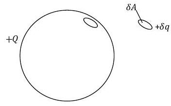
(ii) A conducting, charged sphere has no field inside the surface for a charge $Q$ on the surface, but a field $E_{\text {sphere }}$ on the outside surface. The repulsion of the surface charges will cause an outward force on the surface, which can be expressed as a pressure $P$.

Imagine that this sphere described has a small area $\delta A$ removed, along with its associated charge $\delta q$, determined by the value of $\sigma$ for the sphere, as illustrated in Figure 9. The field lines remain distributed as before since we are not in practice removing the small area.

figure

Figure 9

i. What is the value of the field strength $E_{\mathrm{s}}$ on each side of the area $\delta A$, in terms of $E_{\text {sphere }}$ ?

ii. Hence write down the field strength in the hole at the spherical surface, just inside where $\delta A$ would sit, due to the charge on the rest of the sphere, in terms of $E_{\text {sphere }}$.

iii. Hence what is the force on the charge of the area $\delta A$ when it is in place?

iv. Now derive an expression for the surface pressure on the sphere due to the charge it carries in terms of $E_{\text {sphere }}$ and $\varepsilon_{0}$.

c) [7] An electric field strength of greater than $3 \times 10^{6} \mathrm{~N} \mathrm{C}^{-1}$ causes air to breakdown and conduct. Determine

(i) the radius of the smallest water drop (treated as a conducting spherical shell so that any excess charge resides on the surface) that can be charged to an electric potential of $7000 \mathrm{~V}$,

(ii) the charge, and the surface charge density of the drop.

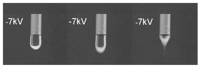
Charged drops of water are produced in a manner similar to that illustrated in Figure 10 with the capillary tube at $-7.0 \mathrm{kV}$. The drop is released vertically and falls under gravity towards an earthed metal plate $10 \mathrm{~cm}$ below the tube where it was formed.

(iii) the speed of the drop when it reaches the earthed metal plate below,

(iv) the average current given a flow rate through the tube of $64 \mathrm{~cm}^{3}$ per hour.

figure

Figure 10: credit: Water with Excess Electric Charge: Leandra P. Santos, Telma R. D. Ducati, Lia B. S. Balestrin, and Fernando Galembeck; J. Phys. Chem. C 2011, 115, 11226-11232

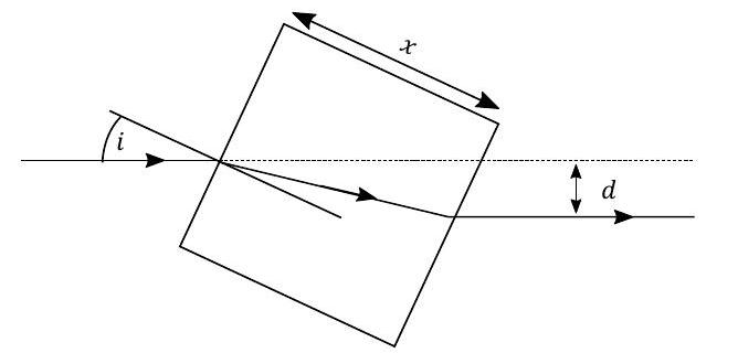
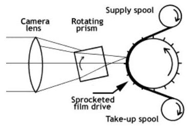
d) [7] The intention is to study the motion of the falling drops by means of high speed photography, and one means of doing this is to use a rotating prism camera shutter. Figure 11 shows the general arrangement for the film passing through the camera at high speed. The continually moving film would blur the image, so a rotating cube of glass is used to move the image for a short time along the film at the same speed as the film travels through the camera. Figure 12 shows a ray of light entering the rotating cube of glass of side $x$, with a refractive index $n$.

figure

Figure 11: credit: (An Overview of High Speed Photographic Imaging by Andrew Davidhazy, School of Photographic Arts and Sciences, Rochester Institute of Technology)

(i) Determine an expression for the lateral displacement $d$, in terms of $x, n$, and the angle of incidence $i$, which should be assumed to be small.

(ii) The prism rotates about an axis perpendicular to the plane of the diagram, such that the image is stationary relative to the moving film. How fast should the film move if $x=5.0 \mathrm{~cm}, n=1.5$ and the cube rotates at $200 \mathrm{~Hz}$ ?

figure
Show answer · 显示答案
Answers
  • (a)(i)$\displaystyle \text{surface}$
  • (a)(iii)$\displaystyle \text{field lines are closer together, the electric field is stronger}$
  • (a)(iv)$\displaystyle q \cdot E_{\mathrm{s}}$
  • (b)(i)$\displaystyle \sigma = \frac{Q}{4\pi r^2}$$\displaystyle E = \frac{Q}{4\pi \varepsilon_0 r^2}$$\displaystyle \frac{\sigma}{\varepsilon_0}$$\displaystyle \frac{\sigma}{2\varepsilon_0}$
  • (b)(ii)$\displaystyle \frac{E_{\text{sphere}}}{2}$$\displaystyle \frac{\sigma^2 \delta A}{2 \varepsilon_0}$$\displaystyle \frac{\sigma^2}{2 \varepsilon_0}$
  • (c)(i)$\displaystyle 2.33 \times 10^{-3} \, \text{m}$
  • (c)(ii)$\displaystyle 1.8 \times 10^{-9} \, \text{C}$$\displaystyle 2.7 \times 10^{-5} \, \text{C/m}^2$
  • (c)(iii)$\displaystyle 1.56 \, \mathrm{m/s}$
  • (c)(iv)$\displaystyle 6.05 \times 10^{-10} \, \mathrm{A}$
  • (d)(i)$\displaystyle d = \frac{x i (n-1)}{n}$
  • (d)(ii)$\displaystyle 21 \, \mathrm{m/s}$

Worked solutions are in the book.
2020 · Q6Electricity & MagnetismModern & Nuclear PhysicsElectric Field in Atoms

This question is about atomic structure and electric fields.

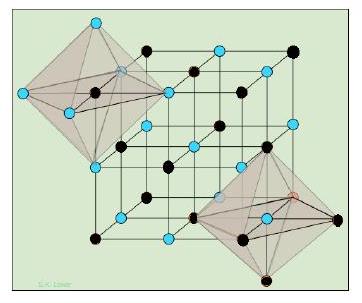
The sodium chloride crystal has a face centred cubic structure and we shall consider a unit cell (smallest repeating unit) which is in the octahedron shown shaded in Figure 11. For the purposes of this question we will consider the upper left octahedron, with the (blue/grey) circles at the corners to be the chlorine ions, and the (black) central ions to be sodium.

The ions in the crystal lattice are held in place by electrostatic forces, and the ions are considered to be point charges. The charge on a sodium ion is $+1 e$; the charge on a chlorine ion, $-1 e$. The distance $a$, between any two adjacent chlorine ions is $0.564 \mathrm{~nm}$.

figure

Figure 11:

credit: Figure attributed to S K Lower, https://doclecture.net/1-49591.html

a) [1] What is the separation between nearest sodium and chlorine ions?

b) [3] Calculate the electric potential energy of the unit cell, considering it to be the building block for the solid, so that you can take its overall charge to be zero and assign an appropriate charge to each chlorine ion. If, in our very simple model, we ignore the interaction between chlorine ions, estimate the energy released when 1 mole of $\mathrm{NaCl}$ is formed.

c) [6] Now consider the octahedron shown in isolation. One sodium ion surrounded by six chlorine ions, the latter which we shall consider to be in fixed positions. If the sodium ion is displaced by a small distance $x$ towards one of the chlorine ions, it will experience a resultant force towards its equilibrium position. Using suitable approximations when $x \ll a$, determine:

(i) An expression, in terms of the electronic charge $e$, the unit cell dimension $a$, the small displacement $x$, and the constants $\pi$ and $\epsilon_{0}$, for the resultant force acting on the sodium ion.

(ii) Estimate the frequency of oscillation, assuming it approximates to simple harmonic motion, and the mass of the ion to be $23 \mathrm{u}$.

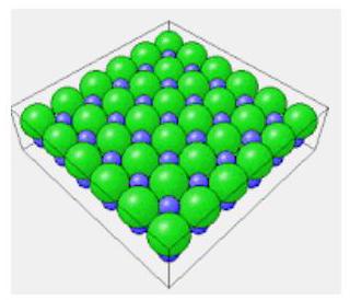
One surface of the sodium chloride crystal looks like Figure 12, and this surface can be investigated using electron diffraction.

d) [8] A beam of electrons accelerated through a potential of $100 \mathrm{~V}$ is directed normally on to the surface. The electrons scatter back elastically from the surface layer of ions. By considering the electrons to behave as waves diffracted by the surface, determine

figure

Figure 12:

credit: http://physicsforeach.blogspot.com/2012/09/oth

(i) an expression for the angle of interference maxima (relative to the normal) along the principle directions shown by the box edges in the diagram. Use the standard notation of: $a$ for the separation of two adjacent scatterers, $n$ for order of diffraction, $\theta$ for diffraction angle of the interference maxima, $m$ for the mass of the electron, $V$ for the potential, and $h$ for Planck's constant.

[Note: it makes no difference if the beam originates on the same side of the surface when it undergoes scattering.]

(ii) Calculate the angle of diffraction for the first and second orders.

Now consider the electron to be a particle with a momentum $p$.

(iii) For the first order diffracted beam, draw a diagram using momentum vectors to show the change in momentum of the electron during collision with the surface. Record the angles between the vectors on your diagram.

(iv) Calculate the direction (relative to the surface) and magnitude of the momentum change.

e) [2] The sodium atom must be ionised to form sodium chloride. The first ionisation energy of sodium is $496 \mathrm{~kJ} \mathrm{~mol}^{-1}$. By considering the outermost electron to lie on the surface of a sphere, within which the remaining charge of the atom is contained, estimate the radius $R$ of the atom.

f) [5] Now consider the sodium atom $(Z=11)$ to consist of a point like nucleus which contains all of the positive charge of the atom, and the electrons each of charge $-e$, evenly distributed within the atom, giving an average charge density of $\sigma$. The radius of the atom is $R$.

(i) Determine an expression for the electric field strength within the atom as a function of distance $x$, from the centre of the atom.

(ii) Subsequently find an expression for the electric potential $V$ within the atom, as a function of distance $x$ from the centre of the atom.

(iii) Finally, by considering the atom to consist of concentric spheres of constant charge density, find an expression for the work done assembling the atom, and provide a numerical estimate of the energy required to turn one mole of sodium into a fully ionised gas (a plasma) of electrons and nuclei.

[Use your result from part (e) for the radius of the atom.]

Show answer · 显示答案
Answers
  • (a)$\displaystyle 0.399 \, \text{nm}$
  • (b)$\displaystyle 347 \, \text{kJ/mol}$
  • (c)(i)$\displaystyle Note$
  • (c)(ii)$\displaystyle 4.4 \times 10^{12} \, \text{Hz}$
  • (d)(i)$\displaystyle \sin \theta_n = \frac{n h}{a \sqrt{2meV}}$
  • (d)(ii)$\displaystyle 12.57^\circ$$\displaystyle 25.72^\circ$
  • (d)(iv)$\displaystyle 84^\circ$$\displaystyle 1.1 \times 10^{-23} \, \mathrm{kg \, m/s}$
  • (e)$\displaystyle 2.8 \times 10^{-10} \, \text{m}$
  • (f)(i)$\displaystyle \frac{Ze}{4 \pi \varepsilon_0} \left[\frac{1}{x^2} - \frac{x}{R^3}\right]$
  • (f)(ii)$\displaystyle \frac{Ze}{4 \pi \varepsilon_0} \left[\frac{1}{x} + \frac{x^2}{2R^3} - \frac{3}{2R}\right]$
  • (f)(iii)$\displaystyle \frac{(Ze)^2}{4 \pi \varepsilon_0} \cdot \frac{3}{10R}$$\displaystyle 1.7 \, \text{MJ/mol}$

Worked solutions are in the book.
2021 · Q3Electricity & MagnetismCircuit: Resistor Network

This question is about the properties of some electrical circuits.

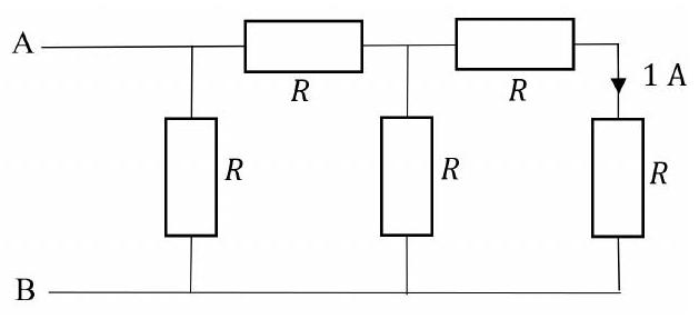
a) [2] The circuit in Fig. 6 shows a chain of identical resistors of value $4.0 \Omega$. A current of 1.0 A flows through the final resistor.

(i) What is the potential difference across AB ?

(ii) What is the equivalent resistance of the chain?

figure

Figure 6

b) [3] A rechargeable cell, modelled as an emf $\mathcal{E}$ in series with an internal resistance $r$, has a current of 0.5 A flowing when a charging potential of 2.5 V is applied. When discharged through a $7.6 \Omega$ resistor, a current of 0.25 A flows.

Determine the emf and internal resistance of the cell.

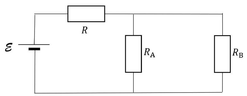
c) [12] A cell of emf $\mathcal{E}$ is connected to a resistor $R$ that is in series with a pair of resistors $R_{\mathrm{A}}$ and $R_{\mathrm{B}}$ as shown in Fig. 7.

figure

Figure 7

(i) For the two resistors $R_{\mathrm{A}}$ and $R_{\mathrm{B}}$ in parallel, show that an expression for the equivalent resistance, $R_{\text {eq }}$ can be written in the form $\frac{R_{\mathrm{A}} R_{\mathrm{B}}}{R_{\mathrm{A}}+R_{\mathrm{B}}}$.

(ii) [2] If a current $I$ was flowing through $R$,

i. what fraction of $I$ would flow through $R_{\mathrm{B}}$, and

ii. give an expression for the current $I_{\mathrm{B}}$ through $R_{\mathrm{B}}$ in terms of $\mathcal{E}, R, R_{\mathrm{A}}$ and $R_{\mathrm{B}}$.

We can use this information to analyse a circuit with more than one source of emf.

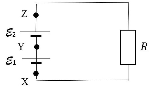
(iii) [1] A simple circuit consisting of two cells in series with a resistor $R$ is shown in Fig. 8.

figure

Figure 8: Two cells in series with a resistor.

i. If cell $\mathcal{E}_{2}$ was removed and points Y and Z joined, what would be the current $I_{1}$ now in the circuit?

ii. If cell $\mathcal{E}_{1}$ was removed instead, and points X and Y joined, what would be the current $I_{2}$ now in the circuit?

If the two cells are both in the circuit, you can see how each source of emf contributes to the current flow. They can be added linearly to give the total current flow.

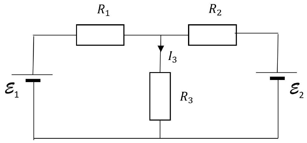
The circuit shown in Fig. 9 consists of two cells $\mathcal{E}_{1}$ and $\mathcal{E}_{2}$ connected to resistors $R_{1}, R_{2}$ and $R_{3}$.

(iv) Remove cell $\mathcal{E}_{1}$ and connect the break in the circuit. Using the notation of this circuit, write down the current flow $I_{3}^{\prime}$ through $R_{3}$.

(v) Replace cell $\mathcal{E}_{1}$ and remove cell $\mathcal{E}_{2}$, connecting the circuit at the break. Write down the current flow $I_{3}^{\prime \prime}$ through $R_{3}$.

(vi) [3] By linearity, $I_{3}=I_{3}^{\prime}+I_{3}^{\prime \prime}$. Write down an expression for $I_{3}$ in terms of $\mathcal{E}_{1}, \mathcal{E}_{2}, R_{1}, R_{2}$ and $R_{3}$.

figure

Figure 9: Two cells and three resistors in a circuit.

(vii) This circuit can also be viewed as two cells in parallel, each with an internal resistance, connected to an external load resistor $R_{3}$. By considering values of $R_{3}$ or otherwise, show that that the cells in parallel behave as a source of emf given by

$$ \frac{\frac{\mathcal{E}_{1}}{R_{1}}+\frac{\mathcal{E}_{2}}{R_{2}}}{\frac{1}{R_{1}}+\frac{1}{R_{2}}} $$

and internal resistance

$$ R_{\mathrm{int}}=\frac{R_{1} R_{2}}{R_{1}+R_{2}} $$

(viii) [6] Using this result, if $\mathcal{E}_{1}=50 \mathrm{~V}, \mathcal{E}_{2}=60 \mathrm{~V}, R_{1}=10 \Omega$ and $R_{2}=15 \Omega$, calculate

i. the value of $R_{3}$ that will dissipate maximum power in $R_{3}$ (this occurs when the load resistor is equal to the internal resistance of the supply), and

ii. determine the value of the maximum power in $R_{3}$.

iii. If the resistance of $R_{3}$ is increased, one cell will begin to charge the other. At what value of $R_{3}$ does this begin to occur?

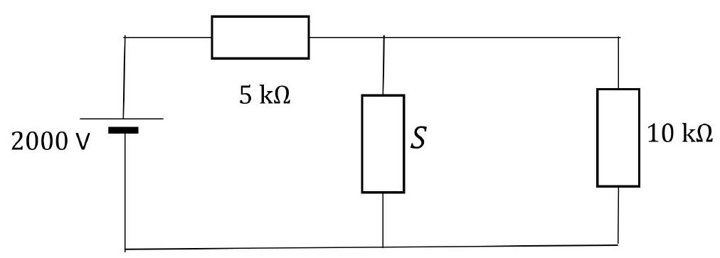
d) [8] Circuits with non-linear components are of great importance. The following circuit of Fig. 10 resembles ones just analysed, but its behaviour is different. The circuit is designed to prevent damage to the device represented by the $10 \mathrm{k} \Omega$ load resistor when the circuit is suddenly connected to a 2000 V d.c. supply. The component $S$ is a voltage suppressor, which has a $V-I$ characteristic given by $I=k V^{2}$, where $V$ is the voltage across $S$ when current $I$ flows through it. The constant $k$ has a value $k=1.0 \times 10^{-7} \mathrm{~A} \mathrm{~V}^{-2}$.

(i) What is the value of the current in the $10 \mathrm{k} \Omega$ load resistor when operating normally?

(ii) A surge in the supply voltage causes the current in the load resistor to double from its normal value. What is the value of the surge voltage from the supply?

figure

Figure 10: A circuit with a voltage suppressor S and a $10 \mathrm{k} \Omega$ load resistor.

Show answer · 显示答案
Answers
  • (a)(i)$\displaystyle 20 \, \text{V}$$\displaystyle 2.5 \Omega$
  • (b)$\displaystyle \mathcal{E} = 2.1 \, \text{V}$$\displaystyle r = 0.8 \, \Omega$
  • (c)(i)$\displaystyle R_{\text{eq}} = \frac{R_A R_B}{R_A + R_B}$
  • (c)(ii)$\displaystyle \frac{I_B}{I} = \frac{R_A}{R_A + R_B}$$\displaystyle I_B = \frac{\mathcal{E} R_A}{R R_A + R R_B + R_A R_B}$
  • (c)(iii)$\displaystyle I_1 = \frac{\mathcal{E}_1}{R}$$\displaystyle I_2 = \frac{\mathcal{E}_2}{R}$
  • (c)(iv)$\displaystyle \frac{\mathcal{E}_2 R_1}{R_1 R_2 + R_1 R_3 + R_2 R_3}$
  • (c)(v)$\displaystyle \frac{\mathcal{E}_1 R_2}{R_1 R_2 + R_1 R_3 + R_2 R_3}$
  • (c)(vi)$\displaystyle \frac{\mathcal{E}_2 R_1 + \mathcal{E}_1 R_2}{R_1 R_2 + R_1 R_3 + R_2 R_3}$
  • (c)(viii)$\displaystyle 6 \, \Omega$$\displaystyle 121.5 \, \mathrm{W}$$\displaystyle 75 \, \Omega$
  • (d)(i)$\displaystyle 0.1 \text{A}$
  • (d)(ii)$\displaystyle 5000 \, \text{V}$

Worked solutions are in the book.
2021 · Q4Electricity & MagnetismElectricity: Electric Field and Conductor

This question is about electric fields.

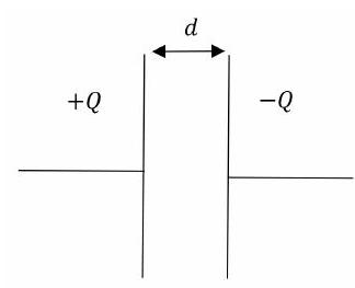
a) [8] A capacitor $C$ consists of two parallel conducting plates, of large area $A$, separated by a distance $d$. A charge $+Q$ is applied to one plate and $-Q$ to the other, as shown in Fig. 11.

(i) Sketch three diagrams, showing the electric field due to one plate alone, the electric field due to the other plate alone, and the resultant electric field when both plates are in place parallel to each other. Neglect edge effects where the field may be non-uniform at the edges of the plates.

figure

Figure 11: A parallel plate capacitor with charges $+Q$ and $-Q$ on the plates.

(ii) Both plates are now positively charged, each with $+Q$ instead. Sketch the three corresponding diagrams of the fields as in part (i).

(iii) The energy of a $+Q$ and $-Q$ charged capacitor can be written in terms of $Q$ and $C$. Given $C=\frac{\epsilon_{0} A}{d}$, and considering the work done in separating the charged plates by $d$, derive an expression for the force $F$ acting between the plates in terms of $Q, \epsilon_{0}$ and $A$.

(iv) Write down an expression for the field strength $E$ between the plates in terms of $\epsilon_{0}$ and $\sigma$, where $\sigma=\frac{Q}{A}$.

(v) If the area of the plates is doubled, by what factor is $Q$ changed to maintain the same force?

(vi) A thunder cloud forms over a large area of still water. What is the electrostatic surface charge density on the water if it rises under the cloud to a height 1.5 mm above its previous level?

b) [10] A point charge $Q$ produces a radial electric field, $E$ at distance $r$ from the charge. The same field strength is obtained at the surface of a sphere of radius $r$ if the charge $Q$ is spread uniformly over the surface, with an area charge density $\sigma=\frac{Q}{4 \pi r^{2}}$.

(i) A conducting sphere of radius $r$ is charged to a potential $V$. Write down an expression for the charge $Q$ on the surface in terms of $V, r$ and $\epsilon_{0}$.

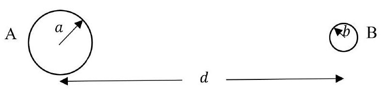
Two spheres A and B of radii $a$ and $b$ respectively are located with a distance $d$ between their centres, with $a, b \ll d$, as in Fig. 12. Each sphere is at the same potential $V$.

figure

Figure 12: Two charged spheres at the same potential.

(ii) How are the electric field strengths at the surfaces of A and $\mathrm{B}, E_{\mathrm{A}}$ and $E_{\mathrm{B}}$ related to each other?

(iii) An ion of charge $-e$ is released from a point 3.0 mm from the surface of B. If $B$ has a radius of 1.0 mm and is at a potentials of 2.0 kV , calculate the energy in electron-volts gained by the ion in moving 1.0 mm towards B

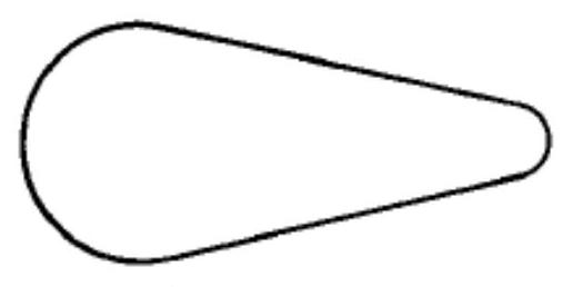
A pear shaped conducting shell with hemispherical ends, as in Fig. 13 is of circular cross section perpendicular to its longitudinal axis. It is positively charged to a potential $+V$.

figure

Figure 13: figure

(iv) Copy the diagram and sketch the pattern of electric field lines near the surface of the conductor.

As the potential is raised, the electric field strength at the surface will increase. The air becomes conducting when an electron is accelerated by the E field so that it gains enough energy between collisions to ionise the next atom with which it collides.

(v) If the ionisation energy is 2.5 eV and the mean free path between collisions is $7.0 \times$ $10^{-6} \mathrm{~m}$, calculate the electric field strength which will cause the air to break down.

(vi) The radii of the two ends of the shell are 15.0 cm and 5.0 cm . What is the maximum potential of the shell such that it will not discharge through breakdown of the surrounding air?

(vii) Sketch the charge distribution over the surface of the shell.

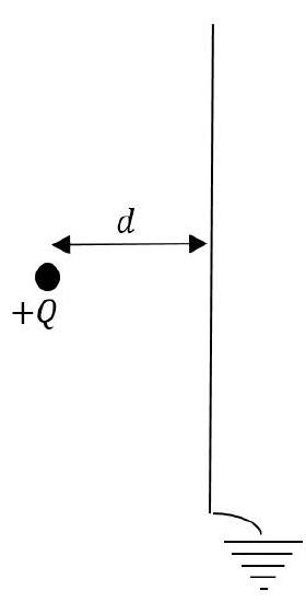
c) [7] A point charge $+Q$ is located a perpendicular distance $d$ from a large area, thin, earthed, conducting plate, as shown in Fig. 14.

(i) Sketch the field lines linking the point charge and the conducting plane.

(ii) Explain

i. why there is a force acting on the plate,

ii. in which direction is the force on the plate, and

iii. why the force vector acting on the plate is along the direction $d$ and passes through the charge $Q$.

(iii) Consider the idea of removing the positive charge on the left and placing a negative charge on the right of the plate at distance $d$.

i. Sketch the field lines between the earthed plate and the negative charge.

ii. Now, by considering these field line patterns, with and without the plate present, calculate the attractive force between a $4.0 \mu \mathrm{C}$ charge located

figure

Figure 14: Point charge near a plane 20 cm from a large, conducting, earthed plate.

Show answer · 显示答案
Answers
  • (a)(iii)$\displaystyle \frac{Q^2}{2 \epsilon_0 A}$
  • (a)(iv)$E_{\mathrm{gap}}=\frac{\sigma}{\epsilon_0}$ (for $\sigma=1\,\mu\mathrm{C/m^2}$, $E\approx1.13\times10^5\,\mathrm{V/m}$). Corrected — the printed σ/(2ε₀) is the field of one plate, not the gap field; see the interactive walkthrough.
  • (a)(v)$\displaystyle \sqrt{2}$
  • (a)(vi)$\displaystyle 16.12 \, \mu \text{C/m}^2$
  • (b)(ii)$\displaystyle \frac{b}{a} E_B$
  • (b)(iii)$\displaystyle 167 \text{eV}$
  • (b)(v)$\displaystyle 3.57 \times 10^{5} \, \text{V/m}$
  • (b)(vi)$\displaystyle 17.85 \, \text{kV}$
  • (c)(iii)$\displaystyle 0.9 \text{N}$

Worked solutions are in the book.
2023 · Q5Electricity & MagnetismThermal PhysicsWaves & OpticsElectricity: Bridge Circuits, Attenuators and Resistive Media

This question is about circuits.

A current-carrying metal strip is taken to a thermal steady state, a vibrating lamp filament is treated as a standing wave, and the heating in a conductor is expressed through the current density. The same circuit ideas are then pushed further: a Wheatstone bridge is balanced against a non-linear lamp, a “T-section attenuator” is tuned for maximum power transfer, and finally the conduction of electricity through a continuous resistive liquid is found by integrating concentric shells.

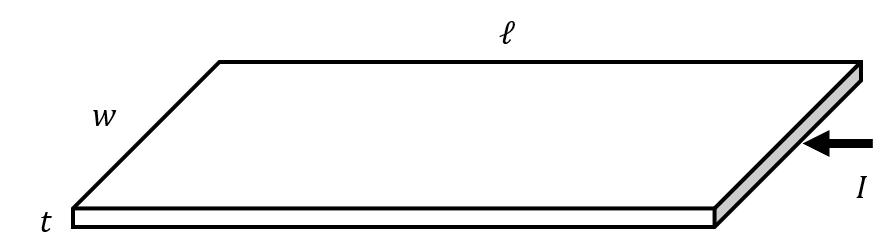
a) [5] A constant potential difference of $2.0\,\mathrm{V}$ is applied across the ends of a metal strip with the following dimensions: length $0.30\,\mathrm{m}$, width $4.0\,\mathrm{mm}$ and thickness $10\,\mu\mathrm{m}$. The metal has a resistivity of $1.5 \times 10^{-7}\,\Omega\,\mathrm{m}$ at $0\,^\circ\mathrm{C}$ and a temperature coefficient of resistance of $\alpha = 3.3 \times 10^{-3}\,^\circ\mathrm{C}^{-1}$. The strip loses heat to its surroundings at a rate proportional to the surface area, and to the excess temperature above the surroundings $\theta$, which are at $0\,^\circ\mathrm{C}$. The constant of proportionality is $22\,\mathrm{W\,m^{-2}\,^\circ C^{-1}}$. Determine:

figure

Figure 16: A current-carrying metal strip of length $\ell$, width $w$ and thickness $t$.

  1. (i) The resistance of the strip at $0\,^\circ\mathrm{C}$.
  2. (ii) The electrical power transferred when the strip is at $15\,^\circ\mathrm{C}$.
  3. (iii) Write down expressions for the power converted as a function of excess temperature $\theta$, and for the rate of heat loss $P$ as a function of excess temperature $\theta$. Hence estimate the temperature reached after the current has been passing for a long period of time.

b) [3] A tungsten filament lamp consists of a long, $25\,\mathrm{cm}$ filament supported at each end and in the middle. When operated using a $50\,\mathrm{Hz}$ supply there appeared to be four loops in the filament. Estimate the tension in the filament given the density of tungsten is $19\,\mathrm{g\,cm^{-3}}$.

c) [2] In a conductor of volume $V$, of uniform cross-section, made of a material of resistivity $\rho$, the current density is $J$ (the current per unit area normal to the flow). Find an expression in terms of $J$, $\rho$ and $V$ for the power dissipated as thermal energy.

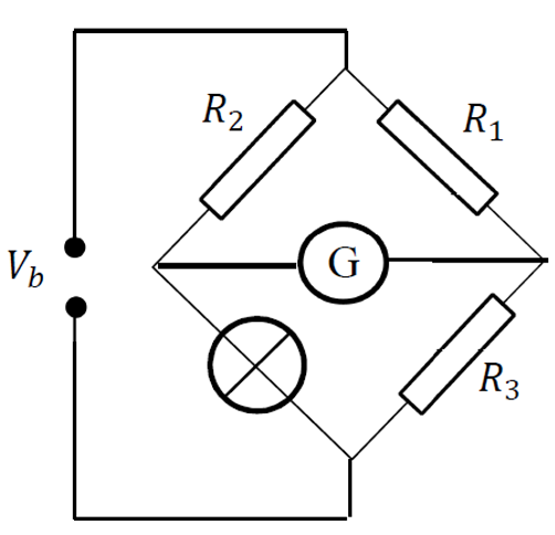
d) [4] The potential difference across a filament lamp, $V$, is related to the current $I$ through it by the relationship $$V = 2I + 8I^2.$$ The lamp is connected to a measurement arm of the bridge circuit shown in Fig. 17. Resistors $R_1$, $R_2$ and $R_3$ each have a resistance of $4.0\,\Omega$. Determine the potential difference $V_b$ such that no current flows through the galvanometer $\mathrm{G}$.

figure

Figure 17: A Wheatstone bridge circuit with a non-linear filament lamp in one arm.

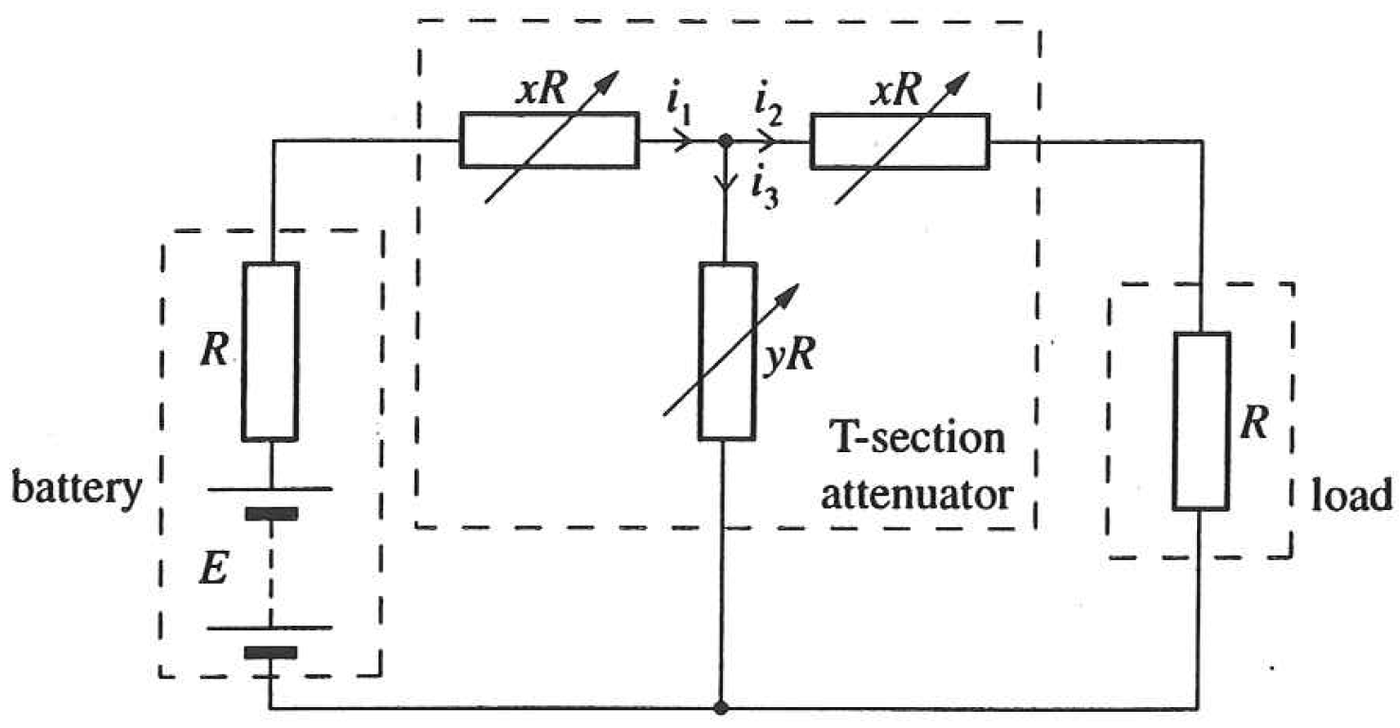
e) [6] The circuit of Fig. 18 includes an element known as a “T-section attenuator”. The attenuator is used to adjust the power delivered to the load. The attenuator is connected to a battery of emf $E$ and internal resistance $R$, and to a load also of resistance $R$. The values of $x$ and $y$ are adjusted until the battery delivers maximum power.

figure

Figure 18: A T-section attenuator between a battery and a load, with series arms $xR$ and shunt arm $yR$.

  1. (i) For this maximum power condition, obtain a relation between $x$ and $y$.
  2. (ii) For the three currents $i_1$, $i_2$, $i_3$ shown in the circuit, obtain a general result for the ratio $\dfrac{i_1}{i_2}$ in terms of $x$ and $y$.
  3. (iii) $P_\mathrm{input}$ is the power delivered at the battery terminals and $P_\mathrm{load}$ is the power dissipated in the load. Show that $$\frac{P_\mathrm{input}}{P_\mathrm{load}} = \frac{f(x)^2}{g(x)^2},$$ where $f(x)$ and $g(x)$ are simple functions of $x$.
Hint: in a circuit of emf $E$ and internal resistance $r$ connected to a load resistance $R$, the condition for the battery to deliver maximum power to the load is when $R = r$.

f) [5] A metal hemisphere of radius $0.1\,\mathrm{m}$ is immersed near the centre of a large conducting tank containing a liquid of resistivity $60\,\Omega\,\mathrm{m}$. The plane surface of the hemisphere is level with the surface of the liquid.

  1. (i) Find an expression for the resistance between two hemispherical shells within the liquid, concentric with the centre of the metal hemisphere, having radii $r$ and $(r + \delta r)$ respectively.
  2. (ii) Hence calculate the resistance between the hemisphere and the tank.
  3. (iii) If the hemisphere is replaced by a sphere in a very large closed container of the liquid, what is the resistance between the sphere and the tank now?
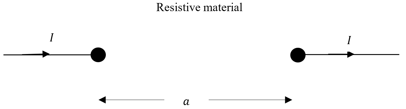
  4. (iv) We now have two small conducting spheres each of radius $r$ separated by a distance $a$ where $a \gg r$, embedded in a resistive material of infinite extent, as in Figure 19. What is the resistance between them? Hint: use the idea of superposition of currents in the material.
figure

Figure 19: Two small conducting spheres of radius $r$, separated by a distance $a \gg r$, embedded in an infinite resistive medium.

Show answer · 显示答案
Answers
  • (a)(i)$\displaystyle R_0 \approx 1.1\,\Omega$
  • (a)(ii)$\displaystyle P \approx 3.4\,\mathrm{W}$
  • (a)(iii)$\displaystyle \theta \approx 57\,^\circ\mathrm{C}$
  • (b)$\displaystyle T \approx 0.6\,\mathrm{N}$
  • (c)$\displaystyle P = J^2\rho V$
  • (d)$\displaystyle V_b = 2.0\,\mathrm{V}$
  • (e)(i)$\displaystyle x^2 + 2xy - 1 = 0, \qquad\text{i.e.}\qquad y = \frac{1 - x^2}{2x}.$
  • (e)(ii)$\displaystyle \frac{i_1}{i_2} = 1 + \frac{x+1}{y} = \frac{x + y + 1}{y}.$
  • (e)(iii)$\displaystyle \frac{P_\mathrm{input}}{P_\mathrm{load}} = \frac{(1+x)^2}{(1-x)^2},$
  • (f)(i)$\displaystyle \delta R = \frac{\rho\,\delta r}{2\pi r^2}.$
  • (f)(ii)$\displaystyle \Delta R \approx 95\,\Omega$
  • (f)(iii)$\displaystyle \Delta R \approx 48\,\Omega$
  • (f)(iv)$\displaystyle R \approx \frac{\rho}{2\pi r}$

Worked solutions are in the book.
2025 · Q3Electricity & MagnetismElectricity: Truncated-Cone Resistance and Diode Circuits

This question is about the arc lamp, the resistance of a truncated carbon cone, and diode circuits.

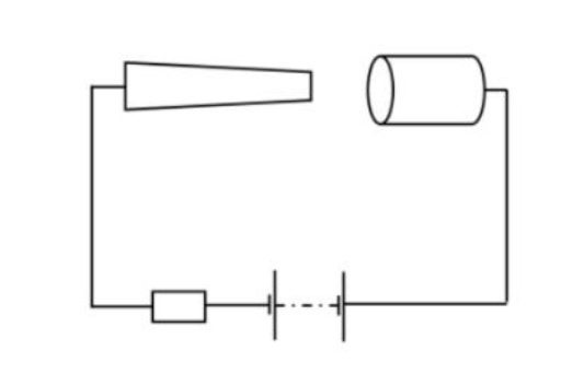
The arc lamp, demonstrated by Humphrey Davy in 1807, produces light from an electric discharge struck between two carbon electrodes. We first model the electrode as a truncated cone and integrate the resistance of a stack of thin discs, then estimate how fast the electrode erodes once it is vaporised by the dissipated power. The second half of the question turns to clamping circuits built from ideal diodes: a single-diode network whose output saturates above a threshold, and a two-diode ladder whose piecewise-linear response is engineered to approximate a smooth quadratic transfer function.

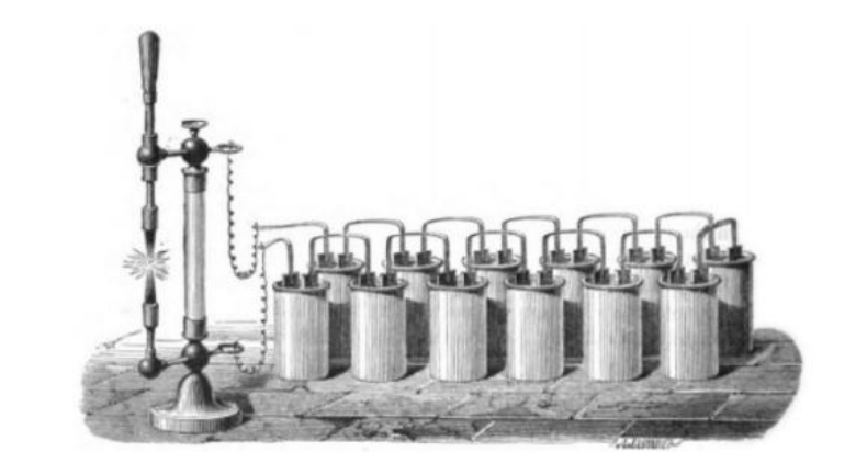
a) [9] The arc lamp was the technique of producing light that was established in the nineteenth century, first demonstrated by Humphrey Davy in 1807. This consisted of two electrodes with a potential difference between them; the heating of the cathode and anode, and of the ionised gas between them, produced light. They continue to have niche uses today.

figure

Figure 5: An arc lamp, with two carbon electrodes between which the discharge is struck.

The electrodes consist of carbon, one of which is a cylinder with a truncated cone shaped end, the other a flat-ended cylinder.

  1. (i) Determine a general expression for the resistance of a truncated cone of carbon with resistivity $\rho$, height $h$ from base to tip, if the base has a radius $a$ and the truncated tip a radius $b$.
    figure

    Figure 6: Deriving the tension in a rotating set of masses.

  2. (ii) If the base radius $= 3.0\,\mathrm{mm}$, the tip radius $= 0.5\,\mathrm{mm}$, the truncated cone height $= 8.0\,\mathrm{mm}$, and the resistivity of the carbon used $= 3.5\times10^{-5}\,\Omega\,\mathrm{m}$, calculate the resistance of the cone.
  3. (iii) When in operation the p.d. across the electrodes is about $50\,\mathrm{V}$ and the current $4.0\,\mathrm{A}$. Assuming that the lamp is highly inefficient and all of the power is transferred as heat to the cylindrical carbon anode of radius $5.0\,\mathrm{mm}$, estimate the erosion of the electrode in mm per minute.

    Latent heat of vaporisation of carbon $= 29.7\,\mathrm{MJ\,kg^{-1}}$
    Density of carbon $= 1600\,\mathrm{kg\,m^{-3}}$

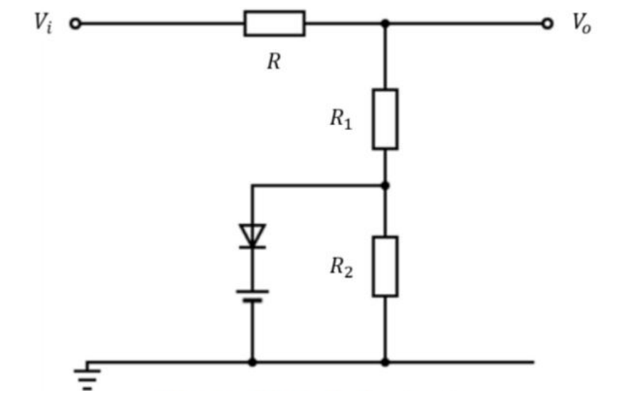
b) [6] In Fig. 7 below, the diode can be considered to have zero resistance when conducting and infinite resistance when non-conducting; the cell provides a source of emf $\varepsilon$ and has negligible internal resistance. The input voltage is $V_i$.

figure

Figure 7: A single-diode clamping circuit with input $V_i$ and output $V_o$.

Derive expressions in terms of $R$, $R_1$, $R_2$ and $\varepsilon$ for the output voltage $V_o$ when the diode is

  1. (i) conducting,
  2. (ii) non-conducting,
  3. (iii) and subsequently find the value of $V_i$ at which the diode starts to conduct.

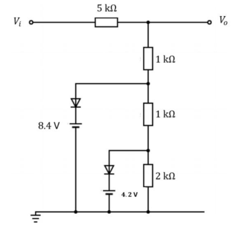
c) [10] The circuit of Fig. 8 is designed to approximately deliver an output voltage $$V_o = \tfrac{1}{2}V_i - \tfrac{1}{250}V_i^2,$$ between $V_i = 0\,\mathrm{V}$ and $V_i = 50\,\mathrm{V}$. The two diodes $D_1$ and $D_2$ may be treated as ideal (zero resistance when conducting, infinite when non-conducting). The input $V_i$ is connected through a $5\,\mathrm{k}\Omega$ series resistor to the output node at which $V_o$ is measured. From this node a chain of resistors runs to the $0\,\mathrm{V}$ rail: $1\,\mathrm{k}\Omega$, then a node $c$, then $1\,\mathrm{k}\Omega$, then a node $b$, then $2\,\mathrm{k}\Omega$. Diode $D_1$ in series with an $8.4\,\mathrm{V}$ source connects node $c$ to the $0\,\mathrm{V}$ rail, and diode $D_2$ in series with a $4.2\,\mathrm{V}$ source connects node $b$ to the $0\,\mathrm{V}$ rail.

figure

Figure 8: A two-diode ladder network engineered to approximate the quadratic transfer function $V_o = \tfrac12 V_i - \tfrac{1}{250}V_i^2$.

  1. (i) Derive expressions for $V_o$, giving the range of $V_i$ that applies in each case when:
    1. i. both diodes conduct,
    2. ii. one is conducting,
    3. iii. neither conduct.
  2. (ii) Determine the difference between $V_o$ produced in the circuit and the function above for $V_i = 0\,\mathrm{V}$ and $V_i = 35\,\mathrm{V}$.

[25 marks]

Show answer · 显示答案
Answers
  • (a)(i)$\displaystyle R = \frac{\rho}{\pi}\,\frac{h}{a-b}\left(\frac{1}{b} - \frac{1}{a}\right)$$\displaystyle R = \frac{\rho h}{\pi a b}$
  • (a)(ii)$\displaystyle R = 0.059\,\Omega$
  • (a)(iii)$\displaystyle \frac{\mathrm{d}\ell}{\mathrm{d}t} \approx 3.2\,\mathrm{mm\,min^{-1}}$
  • (b)(i)$\displaystyle V_o = \varepsilon + (V_i - \varepsilon)\,\frac{R_1}{R + R_1}$
  • (b)(ii)$\displaystyle V_o = V_i\,\frac{R_1 + R_2}{R + R_1 + R_2}$
  • (b)(iii)$\displaystyle V_i > \varepsilon\,\frac{R + R_1 + R_2}{R_2}$
  • (c)(i)$\displaystyle V_o = \frac{4}{9}\,V_i \qquad (0 \le V_i < 18.9\,\mathrm{V})$$\displaystyle V_o = (V_i - 4.2)\,\frac{2}{7} + 4.2 \qquad (18.9\,\mathrm{V} < V_i < 33.6\,\mathrm{V})$$\displaystyle V_o = \frac{V_i - 8.4}{6} + 8.4 \qquad (V_i > 33.6\,\mathrm{V})$
  • (c)(ii)$\displaystyle \Delta V_o\big|_{V_i = 0} = 0\,\mathrm{V}$$\displaystyle \Delta V_o\big|_{V_i = 35} \approx 0.2\,\mathrm{V}$

Worked solutions are in the book.