BPhO R1 S1 · Section 1

Circuits

30 questions — reveal each final answer.

2011 · aCircuits

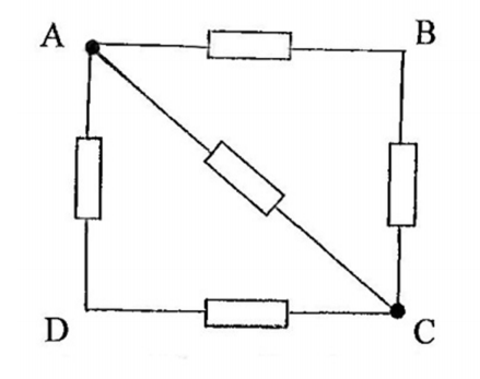
In a circuit the following resistor combination is found.

All the resistors in Figure have resistance $R$ ohms.

What is the total resistance across (i) AC and (ii) AB?

figure
Show answer · 显示答案
Final result
  • The total resistance across AC is $\frac{R}{2}$, and the total resistance across AB is $\frac{5R}{8}$.

Worked solutions are in the book.

2012 · jCircuits

A battery of emf $E$ and internal resistance $r$ drives $3.0$ A round a circuit consisting of two $2.0 \mathrm{ohm}$ resistors in parallel. When these resistors are connected in series the current is $1.2 \mathrm{~A}$. Calculate $E, r$ and the power dissipated, $W$, in each resistor. [5]

Show answer · 显示答案
Final result
  • $E = 6.0\,\mathrm{V}$, $r = 1.0\,\Omega$.

Worked solutions are in the book.

2013 · aCircuits

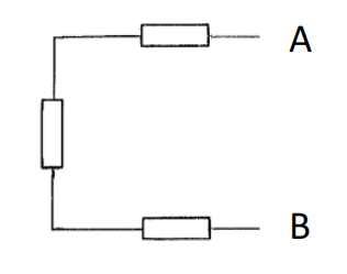
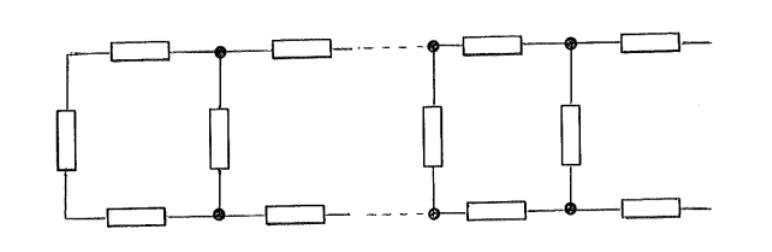
A chain of resistors is composed of $n$ units, each consisting of three resistors, each resistor of resistance $R$. A unit is attached to the left hand end of the chain in order to increase the number of units from $n$ to $(n+1)$.

figure
figure

(i) Calculate the resistance (between $A$ and B) across a chain with two units, $R_{2}$, and the resistance $R_{3}$, across a chain with three units .

(ii) A unit is attached to a long chain. The resistance of the chain, $R_{T}$, is not altered by this addition. Determine the resistance of the chain. [6]

Show answer · 显示答案
Final result
  • For the infinite chain, adding a unit must reproduce the same input resistance, giving the self-consistent (fixed-point) equation $R_T = 2R + (R \parallel R_T)$.

Worked solutions are in the book.

2014 · aCircuits

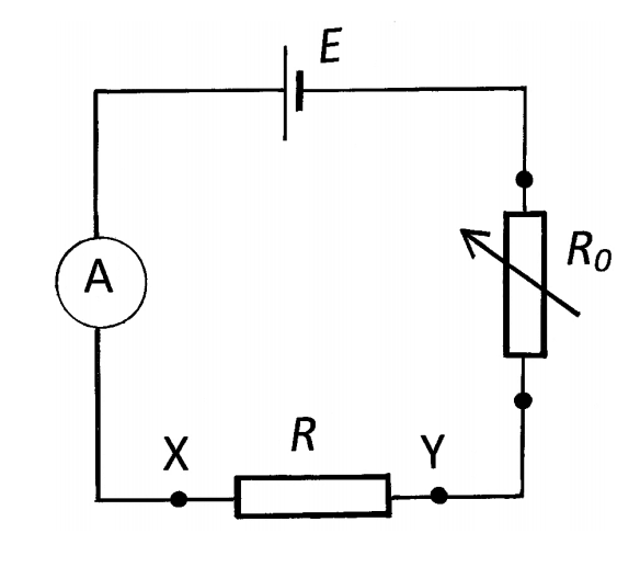
The circuit in Figure contains a cell of emf $E$, a known variable resistance $R_{0}$, an unknown resistance $R$ and an ammeter. When $\mathrm{X}$ and $\mathrm{Y}$ are short circuited $E=I_{0} R_{0}$ When $R$ is inserted the current is $\alpha I_{0}$, where $\alpha$ is a constant.

figure

(i) Express $R$ in terms of $R_{0}$ and $\alpha$, giving the range of validity of $R$ and $\alpha$.

(ii) In order to extend the range of $\alpha$, modify the circuit by putting $R$ in parallel with $R_{0}$. Determine the ranges of $R$ and $\alpha$ for the modified circuit. [4]

Show answer · 显示答案
Final result
  • In the first configuration, $R$ is given by $\frac{R_0(1 - \alpha)}{\alpha}$ with $0 < \alpha < 1$, while in the modified configuration with $R$ and $R_0$ in parallel, $R$ is given by $\frac{R_0}{\alpha -1}$ with $\alpha > 1$.

Worked solutions are in the book.

2015 · hCircuits

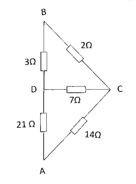
Determine, in the Figure, the total resistances, $R_{\text {TBC }}$, across $B C, R_{\text {TBD }}$ across $B D$ and $R_{\text {TBA }}$ across $A B$. [6]

figure
Show answer · 显示答案
Final result
  • The results are $R_{TBC} = 1.63\Omega$, $R_{TBD} = 2.17\Omega$, and $R_{TAB} = 9.60\Omega$.

Worked solutions are in the book.

2015 · jCircuits

An a.c. voltmeter displays the rms value of the voltage, $V$, for a.c. signals and also for periodic signals that are not sinusoidal. What reading will it display if connected to a periodic voltage, period $4 T$, that changes instantaneously from $+10 \mathrm{~V}$ to $-2 \mathrm{~V}$ to $+4 \mathrm{~V}$ repeatedly, the voltages lasting, respectively, for $T, T$ and $2 T$ ?

Determine the following;

(i) the mean voltage i.e. $V_{\mathrm{m}}$.

(ii) the rms voltage i.e. $V_{\text {rms }}$.

(iii) the rms value of deviation from the mean, $\left(V-V_{\mathrm{m}}\right)$ which is $V_{\mathrm{rmsm}}$. [4]

Show answer · 显示答案
Final result
  • The mean voltage over one period is $4 \, \text{V}$, the RMS voltage is approximately $5.83 \, \text{V}$, and the RMS value of deviation from the mean is approximately $4.24 \, \text{V}$.

Worked solutions are in the book.

2015 · lCircuits

A horizontal square wire loop of side $4.00 \mathrm{~cm}$ has a resistance, $R$, of $2.00 \times 10^{-3} \Omega$. The loop is situated in a vertical downward magnetic field of $0.700 \mathrm{~T}$. When the field is switched off, it decreases to zero, at a uniform rate, in $0.800 \mathrm{~s}$.

Determine:

(i) the induced current, $I$, and its direction in the loop.

(ii) the energy dissipated in the loop. [7]

Show answer · 显示答案
Final result
  • We found that the induced current in the loop is $0.700 \, \text{A}$ in a clockwise direction, and the energy dissipated in the loop over the $0.800 \, \text{s}$ duration is $7.84 \times 10^{-4} \, \text{J}$.

Worked solutions are in the book.

2016 · bCircuits

A charge of $0.5 \times 10^{6} \mathrm{C}$ passes through a $12 \mathrm{~V}$ battery when the battery discharges. Assuming that the p.d. across the terminals remains constant, calculate the time for which it can supply $0.45 \mathrm{~kW}$. [2]

Show answer · 显示答案
Final result
  • The battery stores $6\times 10^6\,\text{J}$, which at $0.45\,\text{kW}$ lasts $1.33 \times 10^4\,\text{s}$ (about $3.7$ hours).

Worked solutions are in the book.

2016 · cCircuits

Draw a general resistive network diagram with:

(i) two resistors in series which are, in turn, in series with three resistors in parallel.

(ii) five resistors that are not in series or parallel, or in a combination of series and parallel arrangements.

Calculate the resistance in (i) and (ii) if all the resistors have resistance $R$. [5]

Show answer · 显示答案
Final result
  • The total resistance for the first configuration is $\frac{7}{3}R$ while for the second configuration, it is $R$.

Worked solutions are in the book.

2017 · hCircuits

A cell, a resistor and an ammeter of negligible resistance are connected in series and a current of $0.80 \mathrm{~A}$ is observed to flow when the resistor has a value of $2.00 \Omega$. When a resistor of $5.00 \Omega$ is connected in parallel with the $2.00 \Omega$ resistor, the ammeter reading is $1.00 \mathrm{~A}$. [5]

Calculate the emf and the internal resistance of the cell.

Show answer · 显示答案
Final result
  • The emf of the cell is $2.3 \, \text{V}$ and the internal resistance of the cell is $0.86 \, \Omega$.

Worked solutions are in the book.

2017 · iCircuits

A battery with an emf of $6 \mathrm{~V}$ can produce a maximum current of $3 \mathrm{~A}$. A resistor is connected to the terminals whose value is such that the power dissipated in it is a maximum. Calculate the maximum energy which can be dissipated in the external resistor in one minute. [4]

Show answer · 显示答案
Final result
  • The maximum energy that can be dissipated in the external resistor in one minute is $270 \, \text{J}$.

Worked solutions are in the book.

2018 · iCircuits

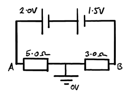
Two resistors and two cells are connected in the circuit shown in Figure. One cell has an e.m.f. of $2.0 \mathrm{~V}$ and an internal resistance of $1.0 \Omega$, the other an e.m.f. of $1.5 \mathrm{~V}$ and an internal resistance of $0.5 \Omega$. The resistors are connected in series and the point between them is at earth, i.e. zero potential. Calculate

(i) the current through the cells,

(ii) the potential difference across each cell, and

(iii) the potential, relative to earth, at points $A$ and $B$. [4]

figure
Show answer · 显示答案
Final result
  • With the midpoint earthed, A sits a voltage drop of $IR_A$ above earth and B a drop of $IR_B$ below it, giving $V_A \approx +1.84\,\text{V}$ and $V_B \approx -1.10\,\text{V}$; the current is $I \approx 0.37\,\text{A}$.

Worked solutions are in the book.

2019 · oCircuits

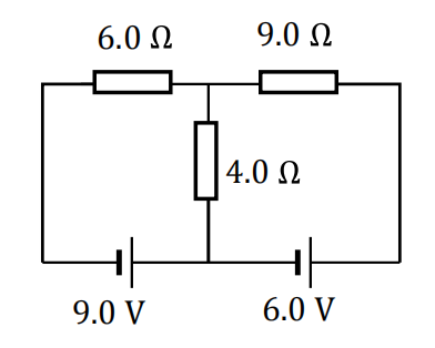
Determine the current in the $6.0 \Omega$ resistor shown in the Fig. The cells have no internal resistance. [5]

figure
Show answer · 显示答案
Final result
  • Therefore, the current in the $6.0\, \Omega$ resistor is $1.24\, \text{A}$.

Worked solutions are in the book.

2020 · iCircuits

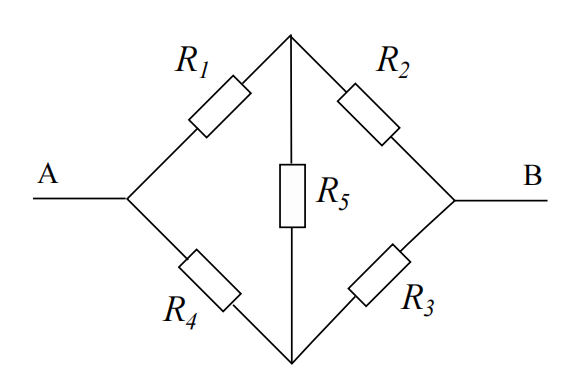
(i). Five resistors, $R_{1} \ldots R_{5}$ are connected in a circuit between points $\mathbf{A}$ and $\mathbf{B}$, as in Figure. Resistors $R_{2}$ and $R_{4}$ can be changed in value to be connecting wires with $R=0$, finite values, or open circuit with $R=\infty$. Write down the values of $R_{2}$ and $R_{4}$ so that the network between $\mathbf{A}$ and $\mathbf{B}$ is equivalent to

i. three resistors in series,

ii. three resistors in parallel, and

iii. two identical resistors in parallel.

figure

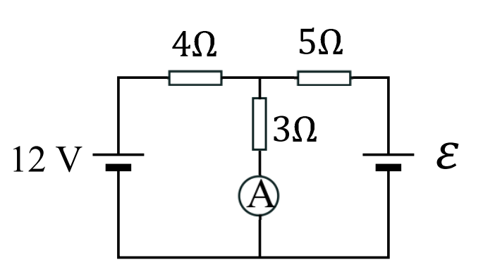
(ii). Figure shows a simple circuit with two cells and three resistors. If the current in the ammeter shown in the figure is $2.0 \mathrm{~A}$ determine the unknown e.m.f. $\varepsilon$, of the battery, assuming the batteries and ammeter have no internal resistance. [4]
figure
Show answer · 显示答案

See the book for the worked solution.

Full worked solutions: the book

2020 · jCircuits

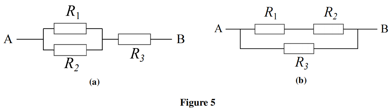
(i). In Figure a, resistors $R_{1}, R_{2}$ and $R_{3}$ are connected between $\mathbf{A}$ and $\mathbf{B}$. Derive an expression for $R_{3}$ in terms of $R_{1}$ and $R_{2}$, if the equivalent resistance, $R_{A B}$ is equal to $R_{1}$.

(ii). A different arrangement is shown in Figure $\mathbf{b}$ for resistors $R_{1}, R_{2}$ and $R_{3}$. Again the equivalent resistance, $R_{A B}=R_{1}$, and the ratio $\frac{R_{3}}{R_{2}}=6$. Determine the value of the ratio of $\frac{R_{1}}{R_{2}}$. [4]

figure
Show answer · 显示答案

See the book for the worked solution.

Full worked solutions: the book

2021 · qCircuits

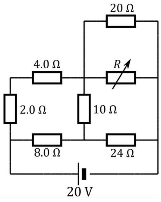
For the circuit shown, what should be the value of the variable resistor $R$ in order to minimise the power converted in the $10 \Omega$ resistor? [3]

figure
Show answer · 显示答案
Final result
  • The value of the variable resistor $R$ that minimizes the power converted in the $10 \Omega$ resistor is $180 \Omega$.

Worked solutions are in the book.

2021 · rCircuits

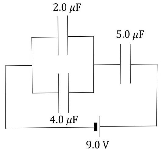
In the arrangement of capacitors in Fig, calculate the charge stored on the $4.0 \mu \mathrm{F}$ capacitor. [3]

figure
Show answer · 显示答案
Final result
  • The charge on the $4.0\,\mu\mathrm{F}$ capacitor is $\tfrac{180}{11} \approx 16.4\,\mu\mathrm{C}$.

Worked solutions are in the book.

2021 · vCircuits

Resistance of a filament light bulb is given by $R=A+B P$ where $A$ and $B$ are constants, and $P$ is the power emitted by the bulb. When operating at $230 \mathrm{~V}$ the power emitted is $100 \mathrm{~W}$. When switched on from cold, the filament has a resistance value $1 / 5$ of its operating resistance, and consequently for the same mains voltage, the power is instantaneously five times greater than when at its normal operating power.

(i) Determine the values of A and B (if you wish, you may leave the answers as products of integer values given).

(ii) What would be the steady emitted power of the bulb if connected to a $210 \mathrm{~V}$ supply? [5]

Show answer · 显示答案
Final result
  • The quadratic for the steady power has two roots; physical reasoning (lower supply voltage gives lower steady power) selects the smaller root, $P \approx 80\,\mathrm{W}$.

Worked solutions are in the book.

2022 · mCircuits

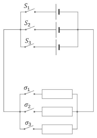
In the circuit shown in Fig. 2, the three cells each supply an emf of $5.0 \mathrm{~V}$ and have an internal resistance of $5.0 \Omega$. The external resistors also each have a resistance of $5.0 \Omega$.

What arrangement of switches gives

(i) the maximum current,

(ii) the minimum non-zero current.

(iii) Determine the current in each case. [3]

figure
Show answer · 显示答案
Final result
  • Maximum current ($1.5\,$A) comes from all cells and resistors in parallel (lowest total resistance); minimum non-zero current ($0.5\,$A) from a single cell driving a single resistor in series (highest total resistance).

Worked solutions are in the book.

2022 · nCircuits

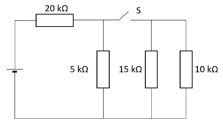
The circuit of Fig consists of four resistors and a switch $\mathbf{S}$. When the $\mathbf{S}$ is open, the current flowing through the $5 \mathrm{k} \Omega$ resistor is $I_{0}$. When $\mathbf{S}$ is closed, the current flowing through the same resistor is $I_{\mathrm{c}}$. What is the ratio $\frac{I_{\mathrm{c}}}{I_{\mathrm{o}}}$, giving your answer as the ratio of two integers.

figure
Show answer · 显示答案
Final result
  • The ratio $\frac{I_{\mathrm{c}}}{I_{\mathrm{o}}}$ is found to be $\frac{3}{5}$.

Worked solutions are in the book.

2022 · vCircuits

A capacitor of value $1.0 \mathrm{~F}$ discharges through a device whose resistance $R$ varies linearly with applied potential difference, $V$, so that $R=A V+B$, where $A$ and $B$ are constants. The resistance of the device has a value of $10.0 \Omega$ when $V=6.0 \mathrm{~V}$, and $4.0 \Omega$ when $V=0.06 \mathrm{~V}$.

The capacitor is initially charged to a potential of $6.0 \mathrm{~V}$.

Determine how long it takes for the capacitor to discharge to $1 \%$ of this initial value. [6]

Show answer · 显示答案
Final result
  • The voltage-dependent resistance makes the time constant change as the capacitor discharges, so the result is not a simple $RC$ exponential; integrating $A + B/V$ gives the discharge time of about $24\,\text{s}$.

Worked solutions are in the book.

2023 · pCircuits

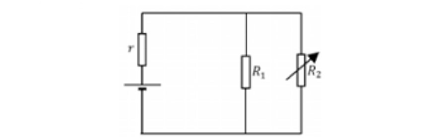
A cell of emf $\varepsilon$ with an internal resistance $r$ is connected across two resistors $R_1$ and $R_2$ in parallel, as in Fig. 6. Resistor $R_2$ is variable, whilst $R_1$ is fixed.
Obtain expressions for
(i) the current $I$ flowing through the cell in terms of $\varepsilon, R_1, R_2, r$,
(ii) the current $I_2$ flowing through $R_2$ in terms of $I, R_1, R_2$,
(iii) the power $P_2$ converted in $R_2$ in terms of $\varepsilon, R_1, R_2, r$.
(iv) By considering the term $\frac{1}{P_2}$ or otherwise, determine an expression for $R_2$ in terms if $R_1$ and $r$ such that the power $P_2$ converted in $R_2$ is a maximum. [5]

figure
Show answer · 显示答案
Final result
  • The power delivered to the load is greatest when the variable resistance equals the resistance of the rest of the network seen from $R_2$, namely $R_1$ and $r$ in parallel, $R_2 = R_1 r/(R_1+r)$ -- the maximum-power-transfer condition.

Worked solutions are in the book.

2023 · qCircuits

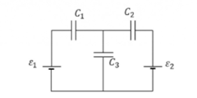
Three capacitors, $C_1, C_2$ and $C_3$ are shown connected to a pair of cells of emfs $\varepsilon_1$ and $\varepsilon_2$ as shown in Fig. 7. Obtain an expression in terms of the capacitor values and the emfs for the potential across $C_3$. It is important that you write down your initial equations clearly. [5]

figure
Show answer · 显示答案

See the book for the worked solution.

Full worked solutions: the book

2024 · kCircuits

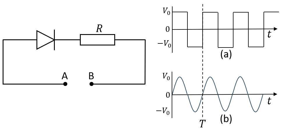
A circuit with an ideal diode in series with a resistor $R$ is shown in Fig. 2. Two supply voltages each with amplitude $V_0$ and frequency $f = \frac{1}{T}$ are also shown: in (a) as a square wave, and (b) a sinusoidal variation with time. Obtain expressions for the average power dissipated in the resistor $R$ for

  • (i) the square wave signal shown in (a), and
  • (ii) for the sinusoidal variation shown in (b).

figure
Figure 2: A diode in series with a resistor $R$, with two a.c. voltage supplies (a) a square wave, and (b) a sinusoidal time dependence. [4]
Show answer · 显示答案
Final result
  • The half-wave rectification halves the available power relative to a full a.c. supply: the square wave gives $P_{\text{av}} = V_0^2/2R$ and the sinusoid $P_{\text{av}} = V_0^2/4R$.

Worked solutions are in the book.

2024 · lCircuits

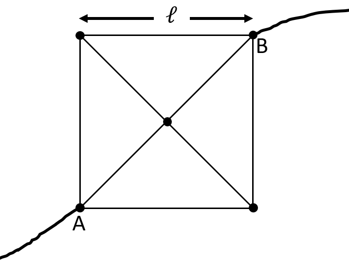
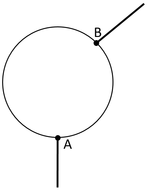
A uniform wire of resistance per unit length $r$ is formed into a square of side $\ell$, with diagonals that are connected at the centre. This is shown in Fig. 3.

Obtain an expression for the resistance between points A and B at the corners of the square, in terms of $r$ and $\ell$. Give your answer in surds.

figure
Figure 3: Wires connected to form a square with diagonals, with connection leads at A and B.

[3]

Show answer · 显示答案
Final result
  • The resistance between opposite corners is $R_{AB} = r\ell\,(2-\sqrt{2}) \approx 0.586\,r\ell$.

Worked solutions are in the book.

2024 · mCircuits

A length of resistance wire of diameter $1.4\,\text{mm}$ and resistivity $3.0 \times 10^{-4}\,\Omega\,\text{m}$ is bent to form a circle, as shown in Fig. 4. The radius of the circle is $10\,\text{cm}$. Two conducting wires are connected at points A and B, such that the contact B can slide around the circle.

  1. (i) Calculate the maximum resistance that can exist between A and B.
  2. (ii) Sketch a graph of the resistance between A and B against the arc length measured from A as contact B is slid from A around the circle and back to A on the other side.
  3. (iii) What is the shortest length of the arc between A and B such that the resistance between A and B is $22.0\,\Omega$?
figure
Figure 4: A wire bent into the shape of a circle with contacts at A and B. B can slide around the circle.

[6]

Show answer · 显示答案
Final result
  • The two arcs form a parallel network, so the resistance is maximal ($\approx 31\,\Omega$) when B is opposite A and symmetric about that point; the shortest arc giving $22.0\,\Omega$ is about $15\,\text{cm}$, all matching the mark scheme.

Worked solutions are in the book.

2025 · eCircuits

A circuit consists of an ideal battery (negligible internal resistance) and three resistors. Two of the resistors labelled $R_A$ have the same resistance and are connected in series with the battery, whilst the third, $R_B$ is connected in parallel with the battery. If $R_B$ and one of the $R_A$ are swapped,

  1. (i) Find the upper limit of the factor by which the power dissipated by the circuit can increase due to this swap.
  2. (ii) If swapping resistors $R_A$ and $R_B$ halves the total dissipated power, what is the ratio $\dfrac{R_A}{R_B}$? [6]

Show answer · 显示答案
Final result
  • The swap can at most double the dissipated power (factor $<2$ strictly, with $2$ as the supremum when $R_B$ dominates).

Worked solutions are in the book.

2025 · fCircuits

A household filament bulb has a rating of $240\,\text{V}$, $60\,\text{W}$, whereas a car filament headlamp bulb is rated at $12\,\text{V}$, $60\,\text{W}$. The filaments of the bulbs are both tungsten, of a similar length, and operate at the same temperature in order to produce the same spectrum. Determine the ratio of the masses of the two filaments. [3]

Show answer · 显示答案
Final result
  • The household (household : headlamp) filament masses are in the ratio $1:400$; the household filament is $400$ times less massive.

Worked solutions are in the book.

2025 · gCircuits

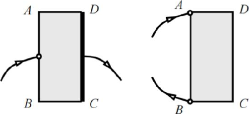
There is a thin rectangular sheet $ABCD$ of uniform resistivity, where $AB = 2BC$, as shown in Fig. 3. Two measurements of its resistance using an Ohmmeter have been made. The first is made across the mid-point of $AB$ and the edge $CD$ (a metal band is connected along $CD$), giving value $R_1$. The second is made between $A$ and $B$, giving value $R_2$. Find the ratio $\dfrac{R_1}{R_2}$. Show your ideas through diagrams.

figure
Figure 3: Resistance of a rectangular sheet

[3]

Show answer · 显示答案
Final result
  • The ratio is $\dfrac{R_1}{R_2} = \dfrac{1}{4}$.

Worked solutions are in the book.

2025 · hCircuits

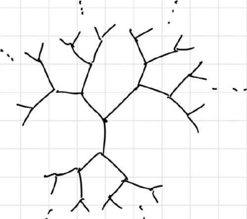
An infinite tree of identical resistors $R$ is constructed as in Fig. 4. Three resistors are each connected to pairs of identical resistors which themselves are each connected to pairs stretching out to infinity. If we have a current entering at the centre of the tree of resistors and the entire outer edge is grounded, what is the resistance of the tree?

figure
Figure 4: Resistance of tree network of identical resistors.

[3]

Show answer · 显示答案
Final result
  • The resistance of the entire infinite tree is $R_{\text{tree}} = \dfrac{2R}{3}$.

Worked solutions are in the book.